Advertisement
Quick Links
Advertisement

Related Manuals for Dorel Home Products Piper 4


Summary of Contents for Dorel Home Products Piper 4
- Page 1 inside for Assembly Manual...
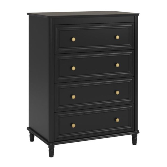
- Page 2 Piper 4 Drawer Dresser Black Cream Keep this Assembly Manual for future reference Two Adults recommended for assembly This product is not intended for commercial use REFERENCE NO: Please retain this booklet as you will be asked to quote this number for any warranty or...
- Page 3 HPlPful HPntP PEOPLE NEEDED FOR ASSEMBLY: 1-2 ESTIMATED ASSEMBLY TIME: 1 HOUR - Open your item in the area you plan to keep it for less heavy lifting - Identify, sort and count the parts before attempting assembly - Compression dowels are tapped in with a hammer - Slides are labeled with a R (right) and L (left) for proper placement - Make sure to always face the point on the top of the Cam Lock towards the outer edge...
-
Page 4: Before You Start
Before You Start Read through each step carefully and follow the proper order Separate and count all your parts and hardware Give yourself enough room for the assembly process Have the following tools: Flat Head Screwdriver, #2 Phillips Head Screwdriver and Hammer Caution: If using a power drill or power screwdriver for screwing, please beware to slow down and stop when screw is tight. - Page 5 Board Identi f cati on Not actual size T6855096010UD T6855096020UD T6855096030UD TOP PANEL LEFT SIDE PANEL RIGHT SIDE PANEL T6855096040UD T6855096050UD T6855096060UD BOTTOM PANEL TOP MOLDING T6855096070UD T6855096080UD T6855096090UD FRONT DRAWER LEFT SIDE DRAWER RIGHT SIDE DRAWER...
- Page 6 Board Identi f cati on Not actual size T6855096100UD T6855096110UD T6855096120UD BACK DRAWER BOTTOM DRAWER DRAWER SUPPORT T6855096130UD T6855096140UD T6855096150UD CENTER MOLDING LOWER BACK PANEL UPPER BACK PANEL...
- Page 7 Part List Actual size TUD0001 TUD0002 TUD0009 TUD0004 TUD0005 CBS 4 x 38 Cam Bolt Cam Lock DOWEL 8 X 25 DOWEL 6 X 25 15-12 TUD0011 TUD0008 TUD0006 PH M4 X 12 CBS 3.5 x 16 NAIL...
- Page 8 Part List Not actual size x4 SET TUD0017 TUD0013 DRAWER SLIDE ROUND KNOB 350 MML x1 set TUD0021 ANTI TIPPING KIT...
- Page 9 Step 1 TUD0001 TUD0021 Attach the Cam Lock. For anti tippinng bracket, do not fully tighten in this step. * raw edges are shaded...
- Page 10 Step 2 x4 (CL) TUD0008 TUD0017 Preparation of left side panel Screw Position * raw edges are shaded...
- Page 11 Step 3 Proper orientation of CAM LOCK TUD0001 TUD0002 TUD0004 Preparation of left side panel * raw edges are shaded...
- Page 12 Step 4 x4 (CR) TUD0008 TUD0017 Preparation of right side panel Screw Position * raw edges are shaded...
- Page 13 Step 5 Proper orientation of CAM LOCK TUD0001 TUD0002 TUD0004 Preparation of right side panel * raw edges are shaded...
- Page 14 Step 6 TUD0004 TUD0002 Preparation of lower back panel & top molding Proper orientation of CAM LOCK * raw edges are shaded...
- Page 15 Step 7 TUD0001 Preparation of front drawer * raw edges are shaded...
- Page 16 Step 8 Proper orientation of CAM LOCK TUD0002 TUD0005 Preparation of left & right side drawer * raw edges are shaded...
- Page 17 Step 9 TUD0005 TUD0002 Preparation of drawer support & center molding * raw edges are shaded...
- Page 18 Step 10 Attach left side drawer to front drawer. * raw edges are shaded...
- Page 19 Step 11 Attach right side drawer to front drawer * raw edges are shaded...
- Page 20 Step 12 Attach drawer support to front drawer * raw edges are shaded...
- Page 21 Step 13 Slotting in bottom drawer * raw edges are shaded...
- Page 22 Step 14 TUD0009 Attach the back drawer with screw * raw edges are shaded...
- Page 23 Step 15 x4 (DR & DL) TUD0008 TUD0017 Attach drawer slide for drawer box * raw edges are shaded...
- Page 24 Step 16 TUD0013 TUD0011 Knob installation * raw edges are shaded...
- Page 25 Step 17 Before start, cover the work floor with any cloth or carton box paper to prevent scratch on board panel edges Attach lower back panel * raw edges are shaded...
- Page 26 Step 18 Attach the center molding. Continue to holding it. * raw edges are shaded...
- Page 27 Step 19 Attach the top molding. Continue to holding it. Note: Hole facing up * raw edges are shaded...
- Page 28 Step 20 Attach the right side panel. * raw edges are shaded...
- Page 29 Step 21 Attach the top panel. * raw edges are shaded...
- Page 30 Step 22 Attach the bottom panel. TUD0009 * raw edges are shaded...
- Page 31 Step 23 Attach the legs to the bottom panel. twist clockwise until fully tighten. * raw edges are shaded...
- Page 32 Step 24 TUD0006 Carefully turn the unit over onto its front as shown. Assure that the unit is square. Distance from corner to corner must be equal as shown. IMPORTANT! THE BACK PANEL IS A STRUCTURAL PART OF THIS UNIT AND MUST BE INSTALLED PROPERLY.
- Page 33 Step 25 For Masonry, Concrete, or other wall materials: Consult your local hardware store for appropriate anchors to securely attach the safety bracket. IMPORTANT: THIS UNIT MUST BE SECURE TO THE WALL TO HELP PREVENT TIPOVER. FOLLOW THESE INSTRUCTIONS TO INSTALL THE ANTI-TIPPING SAFETY BRACKET PROVIDED WITH THIS PRODUCT.
- Page 34 Step 26 Insert the drawer, carfeully align the roller * raw edges are shaded...
-
Page 35: Maximum Loads
Maximum Loads This unit has been designed to support the maximum loads shown. Exceeding these load limits could cause sagging, instability, product collapse, and/or serious injury. 35 lbs. 50 lbs. 15.9 kg 34 kg each drawer Warning: Risk of serious injury to person - do not place a television on this furniture. This furniture is not approved for use with a television.
Need help?
Do you have a question about the Piper 4 and is the answer not in the manual?
Questions and answers