Table of Contents
Advertisement
Quick Links
Advertisement
Table of Contents

Related Manuals for triOS VIPER


Summary of Contents for triOS VIPER
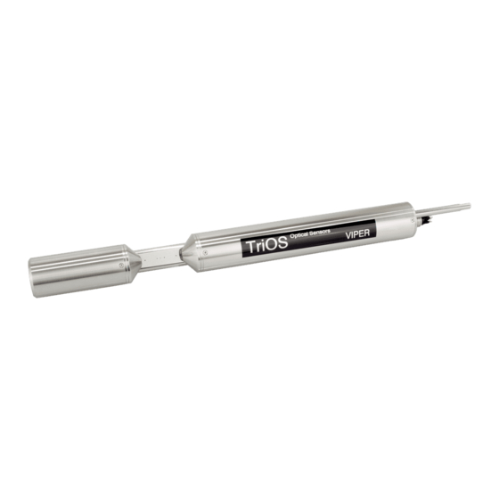
- Page 1 VIPER OPERATING INSTRUCTIONS...
-
Page 3: Table Of Contents
TABLE OF CONTENTS Product Chapter Table of Contents 5 Calibration 1 General Information 5.1 Factory Calibration 1.1 Introduction 5.2 Water Base 1.2 Health and Safety Information 5.3 Customer Calibration 1.3 Warnings 5.4 Measurement Properties 1.4 Users and Operating Requirements 1.5 Intended Use 6 Malfunction and Maintenance 1.6 Disposal Information 6.1 Cleaning and Upkeep... -
Page 4: General Information
We are glad that you have chosen to purchase our VIPER photospectrometer. VIPER is a submersible VIS process spectrophotometer, that is designed for use in industry and science. It may only be used for measuring aqueous solutions, e.g. process wastewater, river water, groundwater and seawater in a temperature range from 2 to 40 °C. -
Page 5: Health And Safety Information
Devices that radiate strong electromagnetic waves can influence the measurement data or result in a malfunc- tion of the sensor. Avoid using the following devices in the same room as the TriOS sensor: mobile phones, cordless phones, transmitters/receivers and other electrical devices that produce electromagnetic waves. -
Page 6: Warnings
Make sure that the cord is not run near hot surfaces. • If the sensor cable is damaged, it must be replaced with an original part by the customer support of TriOS Mess- und Datentechnik GmbH. -
Page 7: Intended Use
General Information 1.5 Intended use The intended use of VIPER consists solely in recording absorbance spectra in the visible range and carrying out photometric measurements at specific wavelengths as described in this manual. In this respect, VIPER is a submersible sensor which can be submerged or used with a flow cell. Observe the technical specifications of the accessories. -
Page 8: Introduction
VIPER measures color at 410 nm as well as SAC 436, SAC 525 and SAC 620 direct in the medium. A filtration of the water is not necessary because the absorbance at a wavelength of 720 nm is used for turbidity correction. -
Page 9: Gost 3351-74_Cr-Co Color
413 nm. VIPER measures color at 413 nm directly in the medium. A filtration of the water is not necessary because the absorbance at a wavelength of 720 nm is used for the turbidity correction. -
Page 10: Measurement Principle And Design
For the optimal use of the sensor, it is recommended to become familiar with the idea and theory underlying the device, as well as with its assembly procedure. VIPER consists of four parts: a defined light source, a lens system, the optical path through the medium, and a spectrometer. -
Page 11: Spectra Calculation
The SAC at the specific wavelength (SAC ) is calculated as shown in Equation 3. In this equation d is the optical path length in millimeter [mm]. For VIPER, optical path lengths of 50 mm, 100 mm, 150 mm and 250 mm are available. -
Page 12: Temperature Correction
2.4.3 Temperature Correction The light intensity of LEDs often varies with temperature. Therefore, a temperature correction factor is deter- mined for each wavelength of the VIPER spectrum and used for the spectrum calculation. 2.5 Parameter and Measuring Ranges The following table provides an overview of the measurement ranges of the detectable parameters in depend- ence on the path length. -
Page 13: Browser
Introduction 2.6 Browser VIPER is equipped with a web interface for sensor configuration and calibration. To access the web interface, you need a G2 InterfaceBox, an Ethernet cable and an Ethernet-enabled device with a web browser, e.g. a notebook / laptop. - Page 14 The link that refers to the page that is currently displayed is always highlighted in the menu. Some of the con- tents and functions are reserved for the employees of TriOS Mess- und Datentechnik GmbH Customer Service. Authentication is needed to access this content. This content is not accessible to every user.
- Page 15 “Settings”. Data logger VIPER is equipped with an internal data logger with a data memory of 2 GB. This allows an almost completely self-sufficient operation over a very long period. The only accessory required is an appropriately dimensioned power supply.
- Page 16 Settings VIPER stores and outputs data in the file formats CSV (Comma Separated Values) and the dat. format. CSV files can be opened in the most common spreadsheet programs. The default configuration is “TriOS Standard”. In this case, numerical values are saved in CSV format and spectra are saved in .dat format. However, you can change this setting and save both in CSV format.
- Page 17 (Measured value - axis shift) x scaling factor = scaled measured value The possibility to scale parameters is given for every parameter that is calculat- ed by a TriOS Mess- und Datentechnik GmbH probe. Parameters should only be NOTICE scaled, if a reference measurement of the medium concerning the parameter is available.
- Page 18 In the subitem “Settings”, settings for the automatic measurement can be made after pressing the “Edit” button: • Comments entered in the “Comment” field can be linked to measured values and spectra. • Automatic measurements can be activated. • An interval for the automatic measurements can be specified. D01-043en202112 Manual VIPER...
- Page 19 To do so, just click on the “Edit” button at the page bottom. The factory settings are: Hardware mode: RS-485 Protocol: Modbus RTU Baud rate: 9600 Flow control: None Parity: None Data bits: 8 Stop bits: 1 D01-043en202112 Manual VIPER...
- Page 20 Introduction VIPER System The “System” page is used for general VIPER configurations. Users can load a calibration file and download the current calibration as a recovery point. Common Settings After pressing the “Edit” button, a comment such as a name or the location of the sensor can be entered here.
- Page 21 • “File not OK”: The calibration file could not be read correctly. Check the path and select the correct file. If the error persists, contact TriOS Mess- und Datentechnik GmbH technical support. • “Device type or serial number does not match”: The calibration file is not suitable for the currently con- nected sensor.
-
Page 22: Commissioning
3.1 Electrical Installation VIPER is designed for 12–24 VDC. With the G2 InterfaceBox a standard 12 or 24 VDC power supply can be used with a minimum output current of 200 mA. If the G2 InterfaceBox is not used, please pay special attention to the pin-setting, as shown in chapters 3.1.1 and 3.1.2. -
Page 23: Fixed Cable With M12 Industrial Plug
To get an open end M12 plug to connect to SCADA or PLC never cut the cable. A suitable socket with open cable ends can be purchased. Always use the 8-pin M12- sensor connector. Please contact TriOS Mess- und Datentechnik GmbH technical support for further information! -
Page 24: Interfaces
3.2.1 Digital Interfaces VIPER provides two lines for digital, serial communication with a control device. It will thereby support the RS- 232 and RS-485 standards. Via the web interface it is possible to switch these standards. Both RS-232 and RS-485 are voltage interfaces. RS-232 voltages are in the range from -15 V to +15 V, RS-485 from -5 V to +5 V, towards GND. -
Page 25: Network
To configure VIPER via various webbrowsers, the TriOS G2 InterfaceBox can be used. The G2 InterfaceBox is both the connection and the power supply for the sensor and can be used with all of the TriOS G2 sensors. The following figure shows a connection to a single sensor:... - Page 26 Make sure that the Ethernet adapter of your device is configured to automatically obtain network settings (IP address and DNS server). Step 2) Plug the M12 connector at the cable end of VIPER into the M12 socket (2) of the G2 InterfaceBox and tighten the screw cap. Step 3) Connect the 12 or 24 VDC power supply to the G2 InterfaceBox to supply power to the sensor.
- Page 27 Like any G2 sensor, VIPER delivers a simple DHCP server as well as a simple DNS server, which is configured exclusively for a direct connection, as described in the previous section. For a complex sensor network, the servers must be supplied by the user.
-
Page 28: Use
Do not add weight to or pull on the sensor cable. VIPER can also be attached with suitable hydraulic clamps, as shown in the following illustration. -
Page 29: Cleaning System
Compressed air cleaning VIPER can be modified with an optional compressed air purge for all path lengths between 50 and 250 mm. The optical path has an air outlet directly at the measuring windows and a hose fitting for the connection of com- pressed air. - Page 30 Be careful not to set the air pressure above 6 bar. Suitable materials for compressed air cleaning for long paths are available from TriOS. To connect the hose, push the hose into the matching connection port. To remove the hose, press the blue locking ring in the direction of the connection and pull the hose out.
-
Page 31: Float
The float is the ideal solution for fluctuating water levels. 4.2 Bypass With the optional flow cell, VIPER can be installed as a bypass. Along with the flow cell, a panel is available on which VIPER and the flow cell can easily be mounted. - Page 32 VIPER Outlet Inlet Since VIPER can be obtained in different path lengths, the dimensions of the associated flow cell vary accord- ingly as described in the following table: used for X [mm] 33,5 LISA UV 10 Path Length [mm] x [mm]...
-
Page 33: Use With A Cuvette
VIPER 4.3 Use with a Cuvette For laboratory use and very small water volumes VIPER can be equipped with a cuvette holder for standard 5 mm cuvettes (see picture below). Measurements with 50 mm and 100 mm cuvettes can also be performed by simply positioning the cuvettes in the optical path. -
Page 34: Calibration
Mess- und Datentechnik GmbH authorized and qualified professionals. Please contact TriOS Mess- und Dat- entechnik GmbH technical support for further information. 1. If the login was successful, VIPER can be calibrated. That means a new water base (zero line) can be recorded. -
Page 35: Customer Calibration
(Raw Value – Offset) x Scaling = Scaled Value (Measured value – Axis Offset) x Scaling factor = Scaled measured value Customer calibration serves as a fine adjustment of the sensor to special media and supple- ments the manufacturer calibration. D01-043en202112 Manual VIPER... - Page 36 4. If there are several laboratory values available, all of the laboratory values should be entered in the graph. Offset = 0 should still be given. As shown in the diagram, the slope of the line is equal to the scaling factor. D01-043en202112 Manual VIPER...
-
Page 37: Measurement Properties
Measuring ranges and detection limits of the scaled parameters depend on the NOTICE scaling factor! 5.4 Measurement Properties Ideally, the optical path of VIPER is chosen so that the absorption at the different wavelengths is between 0.01–2.5 AU. Abs 360 – 720 [AU] 0.01…2,5 2.5…3... -
Page 38: Malfunction And Maintenance
Under no circumstances should the sensor be cleaned with hydrochloric acid. Even very low concentrations of hydrochloric acid can damage stainless steel NOTICE components. In addition, TriOS Mess- und Datentechnik GmbH warns against the use of strong acids, even if the sensor should have a titanium housing. D01-043en202112 Manual VIPER... -
Page 39: Cleaning The Measuring Window
6.1.2 Cleaning the Measuring Window You can clean the window with a lint-free cloth, a clean paper towel or a special optical paper from TriOS Mess- und Datentechnik GmbH with a few drops of acetone. Make sure that you do not touch the window surface... -
Page 40: Maintenance And Inspection
The zero value of the VIPER is checked via the web interface. To access the web interface, you will need the G2 InterfaceBox and an Ethernet-capable device with a web browser, such as a notebook / laptop. - Page 41 0.1 AU for 720nm • 0.2 AU for other absorptions in nm Below these values, you do not need to draw a new zero line, unless there are structures that are clearly inter- fering with the measurement. D01-043en202112 Manual VIPER...
-
Page 42: Troubleshooting
The “Upload” function on the “System” page allows a previously downloaded calibration to be restored or a calibration file created by TriOS Mess- und Datentechnik GmbH service to be installed on the sensor. Enter the storage path for the appropriate calibration file in the “File” field or select it by clicking on the “Browse...”... -
Page 43: Technical Data
RS-232 or RS-485 (Modbus RTU) Power consumption ≤ 3 W Power supply 12...24 VDC (± 10 %) Maintenance effort ≤ 0.5 h/month (typical) Calibration/maintenance 24 months interval System compatibility Modbus RTU Warranty 1 year (EU: 2 years) US: 2 years D01-043en202112 Manual VIPER... - Page 44 +2...+40 °C ~ +36 ˚F to +104 ˚F Ambient temperature +2...+40 °C ~ +36 ˚F to +104 ˚F Storage temperature -20...+80 °C ~ -4 ˚F to +176 ˚F Inflow velocity 0.1...10 m/s ~ 0.33 fps to 33 fps D01-043en202112 Manual VIPER...
-
Page 45: External Dimensions
VIPER Technical Data 7.2 External Dimensions D01-043en202112 Manual VIPER... -
Page 46: Accessories
8.3 VALtub The VALtub is used to check and recalculate the zero values. Due to the adapted shape, only small amounts of water are needed here to make a measurement. D01-043en202112 Manual VIPER... -
Page 47: Warranty
Damage caused by improper handling and use of the device is not covered by the warranty. • Damage caused by modification or unprofessional attachment of accessories by the customer is not covered by the warranty NOTICE Opening the sensor will void the warranty! D01-043en202112 Manual VIPER... -
Page 48: Customer Service
VIPER 10 Customer Service If you have a problem with the sensor, please contact TriOS technical support. We recommend sending the sensor in every 2 years for maintenance and calibration. To do this, please request an RMA form from technical support. -
Page 49: Contact
If you have found a bug in any of our devices or programs, or would like additional features, please contact us: Technical Support: support@trios.de General questions/sales: sales@trios.de Website: www.trios.de TriOS Mess- und Datentechnik GmbH Bürgermeister-Brötje-Str. 25 26180 Rastede Germany Phone... -
Page 50: Keyword Index
Cleaning IP-Address Cleaning systems Compressed air cleaning Contact Copyrights Customer calibration Customer service M12 industrial connector Maintenance Declaration of Conformity Manufacturer calibration Dimensions Measurement properties Disposal Measuring principle Diving operation Measuring window cleaning Electrical installation Electromagnetic waves D01-043en202112 Manual VIPER... - Page 51 Offset User requirements Operating requirements Panel Installation Warnings Parameter Warranty Product identification Waste Reagents Return RMA number Zero value check Zero value determination Safety instructions Scaling factor Scope of delivery Specifications Structure of the sensor SubConn-8pin Plug D01-043en202112 Manual VIPER...
-
Page 52: Faq - Frequently Asked Questions
VIPER is an independent measuring instrument, which can be operated without additional hardware. VIPER setting can be changed via the web interface. To access the web interface, you need the G2 Inter- faceBox and an Ethernet-enabled device with a Web browser, such as a notebook. - Page 53 VIPER D01-043en202112 Manual VIPER...
-
Page 54: Annex
Bürgermeister-Brötje-Str. 25 D- 26180 Rastede Konformitätserklärung Declaration of Conformity Déclaration de Conformité Die TriOS GmbH bescheinigt die Konformität für das Produkt The TriOS GmbH herewith declares conformity of the product TriOS GmbH déclare la conformité du produit Bezeichnung VIPER Product name... - Page 55 Modbus RTU Software Version This Modbus protocol refers to software version 1.0.1 and higher. Serial Interface Upon delivery, VIPER is configured to RS-485 with the following settings: • Baud rate: 9600 bps • Data bits: 8 • Stop bits: 1 •...
- Page 56 Raw / Scaled value for absorbance at 620 nm Float scaled absorbance 1514 in AU Abs720 absorbance / 1016 / Raw / Scaled value for absorbance at 720 nm in Float scaled absorbance 1516 AU (turbidity correction) D01-043en202112 Manual VIPER...
- Page 57 The values of the ordinate of the graph of the Ordinate 2612 Float[Length] last measured spectrum. In general these are the absorption values. The length in [mm] of the optical path of the Waterbase path length 4006 Uint16 waterbase spectrum. D01-043en202112 Manual VIPER...
- Page 58 Trigger measurement 0x0101: Absorption spectrum + Substance analysis Other values are reserved for future purpose. Report slave ID (0x11) The sensor name, serial number and firmware version is replied each as null-terminated ASCII string. Beispiel: 0x00 0x00 0x00 D01-043en202112 Manual VIPER...
Need help?
Do you have a question about the VIPER and is the answer not in the manual?
Questions and answers