Table of Contents
Advertisement
Quick Links
iEM-RS Series Modbus RS485
Integrated Stepper Motor
User Manual
©2022 Leadshine Technology Co., Ltd.
Address: 15-20/F, Block B, Nanshan I Valley, No.3185, Shahe West Road, Nanshan District,
Shenzhen, Guangdong, 518055, China
Tel: (86)755-26409254
Fax: (86)755-26402718
Web:
Sales:
www.leadshine.com
sales@leadshine.com
Support:
tech@leadshine.com
Advertisement
Table of Contents
Troubleshooting

Subscribe to Our Youtube Channel
Related Manuals for Leadshine Technology iEM-RS Series

Summary of Contents for Leadshine Technology iEM-RS Series
- Page 1 Series Modbus RS485 Integrated Stepper Motor User Manual ©2022 Leadshine Technology Co., Ltd. Address: 15-20/F, Block B, Nanshan I Valley, No.3185, Shahe West Road, Nanshan District, Shenzhen, Guangdong, 518055, China Tel: (86)755-26409254 Fax: (86)755-26402718 Web: Sales: www.leadshine.com sales@leadshine.com Support:...
- Page 2 Therefore, information contained in this manual may be updated from time-to-time due to product improvements, etc., and may not conform in every respect to former issues. Thank you for purchasing Leadshine iEM-RS Series Products ◆ Please read this manual carefully before operating ◆...
- Page 3 Series Modbus RS485 Integrated Stepper Motor Safety Precautions Overall Notes Do not remove the housing with the drive powered on. Cables. Connectors and optional equipment. Please disconnect the power supply for at least 2 minutes and make sure the ...
- Page 4 Series Modbus RS485 Integrated Stepper Motor Precautions for Installation Please install the drive in a cabinet that provides fire protection. Electrical protection in the control cabinet. Please install the driver and motor in a position with sufficient weight ...
-
Page 5: Table Of Contents
Table of Content 1 Introduction................................1 1.1 Product Introduction............................1 1.2 Features................................1 1.3 Application Scenarios............................. 1 1.3.1 Hands-on Tuning..........................1 1.3.2 Practical Application Scenarios......................1 2 Specifications................................3 2.1 Electrical and Operating Specifications......................3 2.2 Storage and Installation Conditions........................3 2.2.1 Storage condition..........................3 2.2.2 Operating ambience conditions...................... - Page 6 4.4.2 Drive Alarm Codes and Troubleshooting..................20 4.4.3 Error Clear............................21 4.5 Register Mapping Continuous Read/Write Function................... 21 4.6 S-code Application............................22 4.7 Enable Drive..............................23 5 PR Mode (Indexer Table)............................24 5.1 PR Main Features............................24 5.2 Homing / Return to Zero Position........................ 24 5.2.1 Homing Parameters...........................
-
Page 7: Introduction
1.1 Product Introduction iEM-RS Series is an integrated stepper motor integrated drive, and based on standard Modbus RTU protocol, using RS485 communication can network up to 31 axes. Its built-in PR feature with 16-segment position table (PR Mode) can save additional controllers in most of point-to-point applications, to greatly enhance system reliability and reduce the cost. - Page 8 Series Modbus RS485 Integrated Stepper Motor (2) Controlled by I/O (switch signal or PLC) The user only needs to turn off the switch signal to realize the PR motion, which is simple to control and low-cost design. Users can also use PLC I/O module to realize PR motion, which is more intelligent than switch signal control.
-
Page 9: Specifications
Series Modbus RS485 Integrated Stepper Motor 2 Specifications 2.1 Electrical and Operating Specifications Holding Power Peak Input Frame Length Weight Command Output Max Baud Digital Digital Model Torque Voltage Current Logical Size (mm) (Kg) Source Capability Rate Input Output (N.m) -
Page 10: Interface And Connection
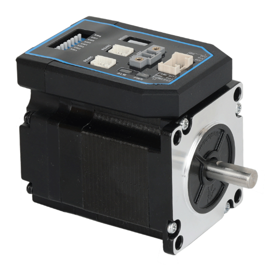
Series Modbus RS485 Integrated Stepper Motor Figure 1: Mechanical specifications 3 Interface and Connection 3.1 Interface 3.1.1 Connectors Definition Name Description Input power connector Digital inputs and outputs connector RS485 communication connector RS232 tuning connector... -
Page 11: Cn1 &Cn2 Input Power Connector
Series Modbus RS485 Integrated Stepper Motor Salve ID: SW1-SW5 SW6-SW7 DIP Switch Baud Rate: Terminal Resistance: SW8 3.1.2 CN1 &CN2 Input Power Connector Name Signal Description 20V- 36V Name Signal Description Configurable Single-ended Digital Inputs DI1-DI7, 12V - 24V. -
Page 12: Cn4-Rs232 Tuning Port
3.1.3 CN4-RS232 Tuning Port Name Signal 3.1.4 DIP Switches The iEM-RS series use an 8-bit DIP switched to set Salve ID (also called Site Alias), Baud Rate and Terminal Resistance, they are shown as below: (1) Slave ID: SW1-SW5 (off=1, on=0) Slave ID... -
Page 13: Wiring Instructions
Series Modbus RS485 Integrated Stepper Motor Note: (1) When the SW1-SW5 is default (all are on), the Slave ID can be configured by the PC software (2) Baud Rate: SW6 - SW7 Baud Rate 115200 (Default) 38400 (Factory) 19200... -
Page 14: Power Supply Cable
Series Modbus RS485 Integrated Stepper Motor Figure 3.1 Wiring Instructions Note: (1) There are two RS485 communication ports above, one of them is input port which connects with master station or previous slave, and the other is output port which connects with the following slave. -
Page 15: Rs485 Communication Cable
Series Modbus RS485 Integrated Stepper Motor 3.2.3 RS485 Communication Cable Leadshine can provide specific network cable CABLE-TX*M*-ISV2, the maximum length is 20meter, user can also made by yourself, please contact Leadshine for the part number of connector. 3.3 I/O Connection 3.3.1 Digital Inputs... -
Page 16: Modbus Rtu
Series Modbus RS485 Integrated Stepper Motor 4 Modbus RTU 4.1 Communication Specifications Items Specifications Remarks Communication RS232 only for fine tuning RS485 and RS232 Port RS485 for motion control Baud Rate 9600/19200/38400/115200[bps] Parameter setting Synchronous Start / Stop Synchronization... -
Page 17: Read Holding Registers Fc= 03
Series Modbus RS485 Integrated Stepper Motor Read Holding Registers Requests content of holding registers Preset Single Register Writes to single holding register Preset Multiple Registers Writes to multiple holding register 4.2.1 Read Holding Registers FC= 03 Read Holding Registers Query (Master to Slave) -
Page 18: Preset Single Register Fc= 06
Series Modbus RS485 Integrated Stepper Motor Message 00 00 00 02 00 00 00 01 00 00 00 04 Slave Number Value of Address Value of Value of Value of Value of Description bytes returned 0x01BC 0x01BD 0x01BE 0x01BF... -
Page 19: Preset Multiple Registers Fc= 10
Series Modbus RS485 Integrated Stepper Motor Details as following: Master->slave data Message: 18 01 22 11 06 06 Description Address Function code Register address Write data CRC check code Slave>master data: Message: 18 01 22 11 06 06 Description... -
Page 20: Modbus & Pr Parameters
Series Modbus RS485 Integrated Stepper Motor Note: (1) In above example, modify the function of DI2 / DI3, and write the value as DI2=0x28 ( means path 0), DI2=0x29 (means path 1); (2) The data type of parameter is 32bit, which include high 16bit register and low 16bit register.usually , we use low 16bits only, but it needs to take the high 16 bits as beginning when we read/write multiple parameters continuously. - Page 21 Series Modbus RS485 Integrated Stepper Motor locking velocity Bit setting: =1: Yes; =0: No bit0: over-current ( Cannot be changed) bit1: over-voltage 0x016D Pr4.22 Alarm detection selection 0-65535 bit3: ADC sampling failure bit4: Locked shaft alarm bit5: EEPROM alarm...
-
Page 22: Input And Output Parameters
Series Modbus RS485 Integrated Stepper Motor Read only: Read value =1 Bit NO. means Bit0 Fault Bit1 Enable 0x1003 Motion status Bit2 Running Bit4 Command completed Bit5 Path completed Bit6 Homing completed Write Function value 0x1111 Reset current alarm... -
Page 23: Smooth Filter Time Setting For Digital Inputs
Series Modbus RS485 Integrated Stepper Motor Note: (1) If the input or output function is set repeatedly, only after the restart drive can detect it. (2) When input functions are configured, it is effective after clicking save and restart drive. -
Page 24: Status Monitoring Parameters
Series Modbus RS485 Integrated Stepper Motor Set value of high 8 bits: Reserved Filter time setting Bit15 Bit14 Bit13 Bit12 Bit11 Bit10 Bit9 Bit8 Reserved bit, write 0 by default Register Value Filtering time (unit: ms) 0000 0001 0010... -
Page 25: Control Word And Status Word
Series Modbus RS485 Integrated Stepper Motor 0x1013 (low 16-bit) 0x1014 (high 16-bit) Feedback position pluses 0x1015 (low 16-bit) 0x1044 (high 16-bit) Profile velocity 0x1045 (low 16-bit) 0x1046 (high 16-bit) Feedback velocity 0x1047 (low 16-bit) 4.3.5 Control Word and Status Word (1) The related function is started by sending the control word, (2) The completion is judged by checking the status word. -
Page 26: Drive Alarm Codes And Troubleshooting
Series Modbus RS485 Integrated Stepper Motor 0x02 Wrong access address 0x03 Wrong data, for example, write data over-limit value, etc. 0x08 Wrong CRC check code Example F: CRC check code error Master-> slave data: Message 00 01 00 01... -
Page 27: Error Clear
Series Modbus RS485 Integrated Stepper Motor Current sampling 1. Restart the drive; 0x40 circuit error 2. If it still exists, the hardware failure Shaft locking 0x80 1. Check whether the motor wire is broken error 1. Connect the drive to Leadshine software to... -
Page 28: S-Code Application
Series Modbus RS485 Integrated Stepper Motor 0x0F18 ← 0x602E (Pr8.46: digital inputs) 0x0F19 ← 0x6203 (Pr9.03: PR0 velocity) At this point, the mapping of the 10 parameter addresses to the mapped area is complete, and the mapped addresses can be used for reading and writing instead of the original parameter addresses. -
Page 29: Enable Drive
The rest of the unused bits are 0, such as bits 11-14, bits 3-6. iEM-RS Series drivers have only 3 outputs, and the S-code can only use 3 bits, each bit corresponds to an output. Therefore, there are only 8 output combinations (000, 001, 010, 011, 100, 101, 110, 111), and these 8 states can be set freely, depending on the requirements. -
Page 30: Pr Mode (Indexer Table)
Series Modbus RS485 Integrated Stepper Motor 5 PR Mode (Indexer Table) PR mode is a single-axis motion control function with 16-segment position table, also called indexer table. It can save the motion control function of the controller. 5.1 PR Main Features... - Page 31 Series Modbus RS485 Integrated Stepper Motor Zero Position: a fixed position on the machine can correspond to a definite digital input signal, or to a Z signal Zero Point of Machine: mechanical absolute zero position Home offset: difference between zero position and zero point of machine, the value of Object 607Ch (default =...
-
Page 32: Homing Parameters
Series Modbus RS485 Integrated Stepper Motor 5.2.1 Homing Parameters Parameters Register address Definition Description Bit0: homing direction =0:CCW; =1:CW. Bit1: move to the Specified point after homing? =0: No; =1: Yes. Bit2: homing type Pr8.10 0x600A Homing mode =0: Homing by detecting limit switch signal... - Page 33 Series Modbus RS485 Integrated Stepper Motor (2) Home Switch at Positive Direction (3) Home Switch & Negative Limit Switch...
-
Page 34: Homing By Limit Switch
Series Modbus RS485 Integrated Stepper Motor (4) Home Switch at Negative Direction 5.2.3. Homing by Limit Switch (1) Positive Limit Switch (2) Negative Limit Switch... -
Page 35: Soft Limit & Jog & Quick Stop
It is not requiring hardware, eliminating malfunction due to poor wiring contact, and it can prevent mechanical slip and abnormal action with internal position comparison. And the iEM-RS Series drives carry out homing to find the mechanical home before the soft limit function can be activated. -
Page 36: Quick Stop
When SI5 is switched on, then SI4 on, and start running on Path 1, refer to Chapter 4.6. 5.3.3 Quick Stop The iEM-RS Series drives have two types of quick stop: digital input quick stop signal and register quick stop. Quick stop time sequence Relevant objects: Register Par. # in... -
Page 37: Pr Path
Series Modbus RS485 Integrated Stepper Motor 0x6002 Pr8.02 Trigger register Write value 0x040---- E-stop; 5.4 PR Path The PR path can be run with single segment movement or continuous movement, which includes three operation modes: position mode, velocity mode and homing mode. There are 16 PR paths, and each path sets the operation modes, the target position, the target velocity, the acceleration and deceleration and the pause time, etc. -
Page 38: Pr Path Configuration
Series Modbus RS485 Integrated Stepper Motor paths paths Similar as above Similar as above Pr9.56- Pr9.63 PR path 7 paths paths Similar as above Similar as above Pr9.64- Pr9.71 PR path 8 paths paths 5.4.2 PR Path Configuration If use the digital input ports to configure the PR path, they can be set to ADD0, ADD1, ADD2 and ADD3, thus forming 16-segment PR path, and then trigger the path number to complete the PR motion. - Page 39 Series Modbus RS485 Integrated Stepper Motor Single path sequence diagram 5.5.3 Multi-segment jump For example: set paths 5 and 9, set path 5 to jump to path 9. Multi-segment jump path sequence diagram Continuous movement The bit5 of Pr9.00 is 0 , which does not overlap the continuous path.
-
Page 40: Trigger Methods
Series Modbus RS485 Integrated Stepper Motor Continuous movement timing sequence (no overlap). Interrupt function The interrupt function is the priority of a PR path. Interrupts a valid path means that interrupting and abandoning the current path under trigger, and runs another path directly, which is similar as Interrupt priority of function.. As below example, interrupt... -
Page 41: Io Combination Trigger
Series Modbus RS485 Integrated Stepper Motor Register Par. # Definition Description address Global Control function of PR: Bit0: CTRG =0: Rising edge trigger =1: Double edge trigger; Bit1: Pr8.00 0x6000 PR control setting =0: Soft limit is invalid =1: Soft limit is valid;... -
Page 42: Fixed Trigger
Series Modbus RS485 Integrated Stepper Motor After triggering SI3, then SI2, SI3, SI4 are “on, on, off”, the path 3 is triggered. After triggering SI3 and SI4, then SI2, SI3, SI4 are “on, on, on”, the path 7 is triggered. - Page 43 Series Modbus RS485 Integrated Stepper Motor The position & velocity& homing and so on are achieved through one data frame. This method uses PR0 to implement, which has 8 data, the last parameter Pr9.07 is mapped to Pr8.02, writing value 0x10 to it will trigger PR0 motion immediately, thus realizing the immediate trigger operation.
-
Page 44: Tuning Operations
Series Modbus RS485 Integrated Stepper Motor 6 Tuning Operations There are three kinds of tuning operations for iEM-RS Series: (1) Through the trial run function of Leadshine's MotionStudio software, (2) Through the PR function of Leadshine's MotionStudio software, (3) Through the general serial port tool software. - Page 45 Series Modbus RS485 Integrated Stepper Motor (5) Basic parameter setting (6) Input and output function and polarity setting...
-
Page 46: Operation Of Trial Run
Series Modbus RS485 Integrated Stepper Motor Note: After setting the parameters, click "OK". Then, in the parameter management window, click the Save button to prevent the parameter values from being lost after the drive is powered off. 6.1.2 Operation of Trial Run... -
Page 47: Operation Of Pr Function
Series Modbus RS485 Integrated Stepper Motor 6.1.3 Operation of PR Function (1) This window can set the CTGR trigger and Homing parameters of PR motion: (2) This window is the PR path parameter setting, including operation mode, target position, speed value, etc. Double click to... - Page 48 Series Modbus RS485 Integrated Stepper Motor After the setting is completed, please click to download and save, as follows (3) Manually run the PR path As shown in the figure below, the default is the motion parameter of PR0. As long as click Start, the motor will run according to...
-
Page 49: Basic Operation Of Serial Port Tools Software
Series Modbus RS485 Integrated Stepper Motor 6.2 Basic Operation of Serial Port Tools Software This is to control the motor through RS485 communication, user can realize the movement of the motor by sending commands to the corresponding registers. 6.2.1 Preparation and Steps... -
Page 50: Operation Instruction Format
Series Modbus RS485 Integrated Stepper Motor (4) Connect tuning software Select COM3, select the same baud rate as the drive settings. After clicking connect. 6.2.2 Operation Instruction Format Data format: Here is an example of setting the PR0 path: (Data is in hexadecimal) -
Page 51: Appendix A Parameters List
Series Modbus RS485 Integrated Stepper Motor 01 06 62 00 00 41 56 42 Set PR mode to relative position mode 01 06 62 01 00 00 C7 B2 Set PR0 position high 01 06 62 02 27 10 2D 8E... - Page 52 Series Modbus RS485 Integrated Stepper Motor 0:CW 0x0007 Pr0.03 Motor direction 1:CCW 0.001m 0x0009 Pr0.04 0-10000 1499 Motor inductance Invalid Software forced enable has a higher priority than IO enable, and when this value is 0, the enable 0x00F Pr0.07...
- Page 53 Series Modbus RS485 Integrated Stepper Motor When SW1 - SW5 are all ON, it can be set by PC 0x01BF Pr5.23 RS485 ID 0-127 software 0: 8-bit data, even check, 2 stop bits; 1: 8-bit data, odd check, 2 stop bits 2: 8-bit data, even check, 1 stop bit;...
- Page 54 Series Modbus RS485 Integrated Stepper Motor (1) Write commands to 0x6002 to select and trigger each action: Write 0x1P (“P” = 0-15 ), run the path P motion; Write 0x20, homing; Write 0x21, manually set to zero position; Write 0x40, quick stop;...
- Page 55 Series Modbus RS485 Integrated Stepper Motor Pr8.62 0x603E S-code output setting for Path 14 Pr8.63 0x603F S-code output setting for Path 15 The corresponding functions can be selected for different bit Bit0-3: TYPE, =0---- no action =1---- position positioning =2---- velocity movement =3---- homing;...
Need help?
Do you have a question about the iEM-RS Series and is the answer not in the manual?
Questions and answers