Table of Contents
Advertisement
Quick Links
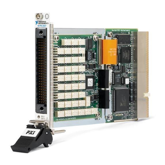
NI PXI-2527 Specifications
32 × 1 Relay Multiplexer
This document lists specifications for the NI PXI-2527
32 × 1 multiplexer relay module. All specifications are subject
to change without notice. Visit
current specifications.
Topologies ...................................... 1-wire 64 × 1 multiplexer,
Refer to the NI Switches Help for detailed topology and
pinout information.
Input Characteristics
All input characteristics are DC, AC
unless otherwise specified.
Maximum switching voltage
Channel-to-channel .................... 300 V
Channel-to-ground...................... 300 V, CAT I
Caution This module is rated for Measurement
Category I and is intended to carry signal voltages
no greater than 300 V. This module can withstand up
to 1,500 V impulse voltage. Do not use this module
for connections to signals or for measurements
within Measurement Categories II, III, or IV.
Caution Do not connect to MAINs supply circuits
(e.g., wall outlets) of 115 or 230 VAC. Refer to the
Read Me First: Safety and Radio-Frequency
Interference document for more information about
Measurement Categories.
for the most
ni.com/manuals
1-wire dual 32 × 1
multiplexer,
2-wire 32 × 1
multiplexer,
2-wire dual 16 × 1
multiplexer,
4-wire 16 × 1 multiplexer
, or a combination
rms
Caution When hazardous voltages
(>42.4 V
/60 VDC) are present on any relay
pk
terminal, safety low-voltage (≤42.4 V
cannot be connected to any other relay terminal.
Caution The maximum switching power is limited
by the maximum switching current, the maximum
voltage, and must not exceed 60 W, 62.5 VA.
Maximum switching power (per channel)
AC systems .................................60 W, 62.5 VA
DC systems .................................Refer to Figure 1
2.50
2.00
1.50
1.00
0.50
0.00
0
50
100 150 200 250 300 350
Figure 1. Maximum Switching Power for DC Loads (per channel)
Maximum total current....................2 A
(switching or carry)
DC path resistance
Initial...........................................<1 Ω
End-of-life...................................≥2 Ω
DC path resistance typically remains low for the life of the
relay. At the end of relay life, the path resistance rapidly rises
above 1 Ω. Load ratings apply to relays used within the
specification before the end of relay life.
/60 VDC)
pk
(up to 60 Hz)
Voltage (V)
Advertisement
Table of Contents

Related Manuals for National Instruments NI PXI-2527


Summary of Contents for National Instruments NI PXI-2527
- Page 1 NI PXI-2527 Specifications 32 × 1 Relay Multiplexer Caution When hazardous voltages This document lists specifications for the NI PXI-2527 32 × 1 multiplexer relay module. All specifications are subject (>42.4 V /60 VDC) are present on any relay to change without notice. Visit for the most terminal, safety low-voltage (≤42.4 V...
-
Page 2: Trigger Characteristics
Open channel isolation (50 Ω termination) Thermocouple Measurement (1-wire and 2-wire) 10 kHz.........>80 dB You can use the NI PXI-2527 and the NI TB-2627 to measure 100 kHz........>60 dB thermocouples. NI software can convert a thermocouple voltage to the thermocouple temperature. For example code, 1 MHz .........>40 dB... - Page 3 † Refer to the Input Characteristics section of this document to determine the thermal EMF value of the NI PXI-2527. For = 2.5 μV), power down the latching relays of the NI PXI-2527. For optimal thermocouple measurement performance (V more information about powering down latching relays, refer to the Power Down Latching Relays After Debounce property in NI-SWITCH or the Power Down Latching Relays After Settling property in NI-DAQmx.
-
Page 4: Physical Characteristics
Table 1. Accessories for the NI PXI-2527 Operating temperature.....0 °C to 55 °C Accessory Manufacturer Part Number Note If you are using the NI PXI-2527 with the NI TB-2627 terminal 779358-01 NI PXI-101X or the NI PXI-1000B chassis, block operating temperature for the NI PXI-2527 is... - Page 5 KREF0 COM0 CH15 + CH15 – CJTEMP (in TB-2627) 1WREF0 KBC01 KHSELECT1 CH16 + CH16 – COM1 KREF1 CH31 + CH31 – 1WREF1 Figure 2. NI PXI-2527 Configuration (Relays Shown in Power-On State) © National Instruments Corporation NI PXI-2527 Specifications...
-
Page 6: Electromagnetic Compatibility
WEEE recycling center. For more information about WEEE recycling • EN 61326 EMC requirements; Minimum Immunity centers and National Instruments WEEE initiatives, • EN 55011 Emissions; Group 1, Class A visit ni.com/environment/weee.htm •... - Page 7 National Instruments, NI, ni.com, and LabVIEW are trademarks of National Instruments Corporation. Refer to the Terms of Use section on ni.com/legal for more information about National Instruments trademarks. Other product and company names mentioned herein are trademarks or trade names of their respective companies. For patents covering National Instruments products, refer to the appropriate location: Help»Patents in your software, the patents.txt file on your CD, or ni.com/patents.
- Page 8 NI PXI-2527 仕様 × リレーマルチプレクサ × NI PXI-2527 32 (>42.4 V /60 VDC) このドキュメントには、 マルチプレ 注意 危険電圧 がリ クサリレーモジュールの仕様が記載されています。 すべ レー端子に接続されている場合、安全低電圧 42.4 V /60 VDC) ≤ ての仕様は事前の通知なしに変更されることがありま をその他のリレー端子に す。 最新の仕様については、 を参照 接続することができません。 ni.com/manuals してください。 注意 最大スイッチ電力は、最大スイッチ電 × ..........トポロジ 単線式...
- Page 9 ....500 G Ω (300 V) チャンネル間 漏れ ~ ....... 150 ns 最小パルス幅 –3 dB 50 Ω 帯域幅( 、 終端) ..........>30 MHz 単線式 NI PXI-2527 メモ は、デジタルフィルタを無 ..........>25 MHz 線式 150 ns 効にすると 未満のトリガパルス幅を認 50 Ω 識します。 デジタルフィルタを無効にする方 チャンネル間絶縁( 終端) 法については、 『...
- Page 10 ラーを計算します。 = 0.063 + 0.5 ℃ ℃ – ⎛ ⎞ = 0.563 ℃ ------------------- ⎝ ⎠ – 熱電対エラーを測定する = NI PXI-2527 の接触電位によるエラー NI PXI-2527/TB-2627 システムとは関係なく、熱電対エ 測定された温度(摂氏) ラーは ±温度範囲 または ±測定の割合の大きいほうの ℃ 値となります。 に対応する電圧 に対応する電圧 この例では、 ℃の測定に標準レベルの タイプ熱 = NI PXI-2527 電対が使われています。この熱電対のエラーは、...
- Page 11 13.0 cm 要があります。 他社製コネクタの安全適合指 × × (8.5 5.1 in.) 令、また該当する基準( 、および北米では 、ヨーロッパでは を含む)に従った ............209 g (7.4 oz) 重量 使用方法を確認してください。 環境 1 NI PXI-2527 表 対応のアクセサリ ..........0 動作温度 ~ ℃ アクセサリ 製造元 製品番号 NI PXI-101 NI PXI-1000B メモ または...
- Page 12 CH0 + KCJTEMP CH0 – KREF0 COM0 CH15 + CH15 – CJTEMP (in TB-2627) 1WREF0 KBC01 KHSELECT1 CH16 + CH16 – COM1 KREF1 CH31 + CH31 – 1WREF1 2 NI PXI-2527 図 構成(電源投入時のリレーを表示) © National Instruments Corporation NI PXI-2527 仕様...
- Page 13 • EN 61326 EMC 必要条件:最小イミュニティ ni.com/ (英語)を参照して environment/weee.htm • EN 55011 Group 1 Class A エミッション: 、 ください。 • C-Tick ICES FCC Part 15 、 、 、 エミッション : Class A メモ このデバイスは、 要件に適合す るため、製品ドキュメントに従って操作して ください。 NI PXI-2527 ni.com/jp 仕様...
- Page 14 National Instruments Corporation 、 、 、および は National Instruments (米国ナショナルインスツルメンツ社)の商標です。 の商標の詳細については、 Terms of Use の「 」セクションを参照してください。本文書中に記載されたその他の ni.com/legal National Instruments 製品名および企業名は、それぞれの企業の商標または商号です。 の製品を保護 する特許については、ソフトウェアに含まれている特許情報(ヘルプ→特許情報) 、 に含まれている ファイル、または のうち、該当するリソースから参照してください。 patents.txt ni.com/patents 374043F-01 2007 年 月 © 2005–2007 National Instruments Corporation. All rights reserved...
Need help?
Do you have a question about the NI PXI-2527 and is the answer not in the manual?
Questions and answers