Table of Contents
Advertisement
Quick Links
Advertisement
Table of Contents

Related Manuals for amber connect Amber Govern T400-m


Summary of Contents for amber connect Amber Govern T400-m
-
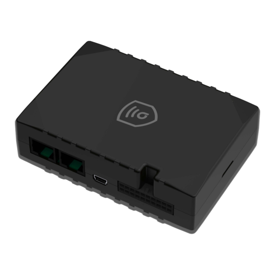
Page 2: Know Your Device
Know your device AGT400-M Device view Pinout AGT400-M pinout Pin name Description number GND (-) Ground CAN 1L SAE J1939 CAN interface Low channel 1 1WIRE POWER Power supply pin for Dallas 1-Wire® devices DIN4 Digital input, channel 4 DIN2 Digital input, channel 2 CAN 2L SAE J1939 CAN interface Low channel 2... -
Page 3: Wiring Scheme
DIN3 Digital input, channel 3 Digital input, channel 1. DEDICATED FOR IGNITION IGN (DIN1) INPUT CAN 2H SAE J1939 CAN interface High channel 2 AIN1 Analog input, channel 1. Input range: 0-30V/0-10V DC Digital output. Open collector output OR Analog input, DOUT4/AIN4 channel 4. -
Page 4: Mounting Recommendations
Unscrew screws Cover removal SIM card insert Battery connection Attaching cover back Device is ready Mounting recommendations • Connecting wires 1. Wires should be connected while the module is not plugged in. 2. Wires should be fastened to the other wires or non-moving parts. Try to avoid heat emitting and moving objects near the wires. -
Page 5: Led Indications
• Connecting power source 1. Be sure that after the car computer falls asleep, power is still available on chosen wire. Depending on car, this may happen in 5 to 30 minutes period. 2. When the module is connected, measure the voltage again to make sure it did not decrease. 3. - Page 6 Status LED indications Behaviour Meaning Blinking every second Normal mode Blinking every two seconds Sleep mode Blinking fast for a short time Modem activity Device is not working or Device is in boot mode Characteristics Basic characteristics Module Name AGT 400-M Technology LTE CAT M1/NB-IoT/GSM/GPRS/GNSS GNSS...
- Page 7 Specification 5.0 + LE Temperature and Humidity sensor, Universal BLE sensors Supported peripherals support Interface Digital Inputs Digital Outputs Analog Inputs 1-Wire temperature sensors 1-Wire iButton RS232 RS485 CAN J1939 J1708 K-Line LVCAN/ALLCAN GNSS antenna External High Gain GSM antenna External High Gain 2.0 Mini-USB LED indication...
-
Page 8: Electrical Characteristics
Digital Input 1, Accelerometer, External Power Voltage, Ignition detection Engine Operating humidity 5% to 95% non-condensing Ingress Protection Rating IP41 Electrical characteristics Value Characteristic description Min. Typ. Max. Unit Supply Voltage Supply Voltage (Recommended Operating Conditions) Digital Output (Open Drain grade) Drain current μA (Digital Output OFF) -
Page 9: Certification And Approvals
This message contains information on how to operate AGT400-M safely. By following these requirements and recommendations, you will avoid dangerous situations. You must read these instructions carefully and follow them strictly before operating the device! • The device uses SELV limited power source. The nominal voltage is +12 V DC. The allowed voltage range is +10...+30 V DC. -
Page 10: Warranty Disclaimer
Directive 2014/53/EU (RED). Warranty Amber connect guarantees its products to be free of any manufacturing defects for a period of 24 months. With additional agreement we can agree on a different warranty period, for more detailed information please contact our sales manager.
Need help?
Do you have a question about the Amber Govern T400-m and is the answer not in the manual?
Questions and answers