
Related Manuals for Herz firematic PELLET 120


Summary of Contents for Herz firematic PELLET 120
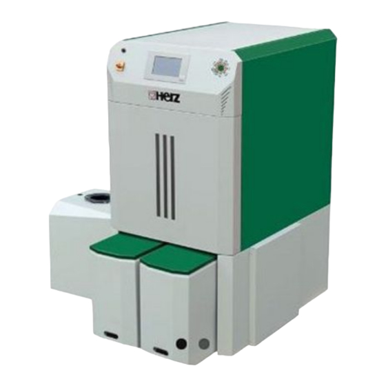
- Page 1 OPERATING INSTRUCTIONS Wood chips & pellets heating system firematic PELLET 120-201...
- Page 2 Your heating system is powered by a HERZ firematic boiler system and we are pleased to be able to count you as one of our many satisfied owners of a HERZ system. The HERZ boiler is the result of years of experience and continuous improvement.
-
Page 3: Table Of Contents
Table of content TABLE OF CONTENT Page page 9.11 Module configuration ....... 30 SAFETY NOTES ........4 9.12 Terms and definitions ......30 Basic safety information ......5 9.12.1 Boiler ............31 Installation ..........5 9.12.2 Buffer ............37 Operation and maintenance ....... 5 9.12.3 Hot water tank.......... -
Page 4: Safety Notes
◼ Should you have any queries, please call us on +43 3357 / 42840-840. ◼ Initial commissioning must be carried out by the HERZ Customer Service department or an authorised specialist (otherwise any warranty claim will not be applicable). ◼... -
Page 5: Basic Safety Information
Therefore the chimney must available from HERZ on request. be designed and produced in accordance with DIN 18160 or EN 13384. When the boiler is... -
Page 6: Maintenance
HERZ. recommended to be carried out regularly by People (including children) who, because of their authorised personnel or by the HERZ Customer physical, sensory or mental capabilities or Service department. -
Page 7: Fuels
Fuels FUELS ◼ The HERZ firematic boiler should be operated Mechanical Strength (DU), EN 17831-1 at as-delivered condition in m-%: DU 97,5 ≥ with the fuels and their properties which are described in this chapter. 97,5 ◼ Diameter 6 mm... -
Page 8: Safety Devices
5 Safety valve ◼ The safety valve automatically releases, when the The load pumps are being controlled by the HERZ Control. The so-called excess pressure or temperature exceeds preset limits. The safety valve has to release at the maximum temperature... - Page 9 Safety devices Figure 4. 1: Safety devices Safety temperature limiter Quench water container Feeding pipe valve Burn back protection device Safety valve connection Safety heat exchanger connection Safety contact ash container and combustion chamber door...
-
Page 10: System
If all room discharge and storage room filling systems of HERZ would be presented, the scope of this guide would be exceeded considerably. More information can be provided by the company HERZ. -
Page 11: Boiler
System Boiler firematic 120 – 201 Fig. 5.2: components firematic 120-201 Burn back protection device The burn back protection prevents burn back in the fuel storage room. It separates additionally the combustion chamber and the fuel storage room. Integrated control The system is controlled and operated centrally via a user-friendly touch display on the firematic boiler. -
Page 12: Mode Of Operation
Mode of operation MODE OF OPERATION process, the pellets are conveyed via the suction Feeding system tube into a separator. The fuel is fed from the fuel storage room by the From the storage tank, the pellets are first room discharge system to the burn back transported via the chute with a screw conveyor protection device (BFP). -
Page 13: Commissioning
The chimney must be insensitive to moisture and Note! calculated and dimensioned according to DIN 4705 or EN 13384 . HERZ does not carry out All guarantee or warranty claims are invalidated in chimney calculations. The chimney calculation the event of damage by corrosion arising due to must be calculated by authorised personnel. -
Page 14: Operating Conditions
Operating conditions is reached, the boiler will switch to the regulation OPERATING phase. CONDITIONS Regulation phase Heating off During regulation phase boiler is During this phase the boiler is switched off, i.e. the modulated between nominal load and partial load. burner is blocked. - Page 15 Flame monitoring (burning chamber the boiler will start up and heat up to minimum boiler temperature 65 °C. temperature) If the burning chamber temperature fluctuates Lambda control greatly during operation, the boiler will switch off. The amount of material and the rotation speed of the ID-fan are controlled by the lambda control.
-
Page 16: Temperature Manager
Temperature manager TEMPERATURE MANAGER The heat demand of the individual modules (boiler, hot water tank, heating circuit, solar, etc.) is controlled by the temperature manager. The below-mentioned scheme explains the functionality of the temperature manager. From the individual modules the MUST-temperature is determined and to that an adjustable temp. increase is added. - Page 17 Temperature manager If the required buffer-top-temperature (required temperature) is higher than the sum of buffer-bottom-MUST- temperature and the set difference, then the required boiler temperature is the result of the required buffer- top-temperature (required temperature) + the adjusted temp. increase (see Fig.8.2). Caution: Consider the set minimum requirement.
- Page 18 Temperature manager If there is no buffer in the system, then the MUST-temperature from the individual modules is determined and to that an adjustable temp. increase is added. The highest of these temperatures is the boiler-MUST- temperature. To this an adjustable hysteresis is added and the result is the boiler-END-temperature (see Fig. 8.4).
- Page 19 Temperature manager Fig. 8.6: Example temperature manager when time mode without difference...
-
Page 20: Control
T-CONTROL T-CONTROL The handling and menu navigation are described in this chapter. Every single T-CONTROL parameter is explained in chapter 9.11. Figure: T-CONTROL Starting the system To switch on the display, two conditions must be fulfilled: ◼ The boiler must be connected to the power supply (see figure below) ◼... -
Page 21: Operation And Handling
T-CONTROL Operation and handling The touch panel is a touch-sensitive screen and control unit. By touching the screen you can change released values or move to other pages. The screen navigation and input can be done with finger, pen, pencil, etc. Main menu After start up, this picture will appear. -
Page 22: Symbols Explanation
T-CONTROL Symbols explanation In this section important symbols are explained. This symbol shows that remote access is currently taking place. This symbol shows that an e-mail is currently being sent. This symbol shows that a USB stick is currently connected. The CHIMNEY SWEEPING FUNCTION provides a test mode for the chimney sweeper. -
Page 23: Code - Entry
T-CONTROL Code – entry If entering the code, the following operations can be performed: ◼ Setting up values ◼ Activation of the aggregate-test ◼ Navigation in the menu settings Navigation 1: Navigation 2: Screen: Screen: By pressing the button: Note: Enter the corresponding code (see below) and press Figure Editor is displayed „OK“... -
Page 24: Switching The Boiler On And Off (Chimney Sweeping Function)
T-CONTROL Switching the boiler on and off (chimney sweeping function) SWITCH-ON SWITCH-OFF Navigation: Navigation: Screen: Screen: By pressing the button: By pressing the button: the boiler will be switched on. the boiler will be switched off. the boiler will switch off, remains the boiler remains on and the off and the previous page will be previous page will be displayed. -
Page 25: Date And Time
T-CONTROL Date and time Navigation 1: Navigation 2: Screen: Screen: By pressing the button: By pressing the button: the language can be set up. the language can be set up. the server name can be set up. (The server receives the time can be set up. -
Page 26: Main Menu Values
T-CONTROL Main menu values 9.8.1 Adding / defining display values Code – entry Navigation 1: Navigation 2: Show value Screen: Screen: By pressing the button: By pressing the button: the selected value can be an overview of available values add favourite Act. -
Page 27: Delete Values
T-CONTROL Navigation 3: Load scheme Navigation 4: Show value BOILER 000 Screen: Screen: By pressing the button: Note: The values of the default scheme can also be Boiler-must, the value will be confirmed and adapted individually. Thereby press 3-5 seconds on Power, Back displayed at the main menu. -
Page 28: Fault Messages And Warnings
T-CONTROL Fault messages and warnings Navigation: → Screen: By pressing the button: the current fault messages will be displayed. (By default, current errors are always Actual displayed first) Archive all fault messages will be displayed. Note: ◼ A red highlighted field represents an active fault (appears in the lower left box). ◼... -
Page 29: Modules
T-CONTROL 9.10 Modules Navigation: → Screen: By pressing the button: the „boiler values“ menu will be displayed BOILER the „buffer values“ menu will be displayed Buffer the „hot water tank values“ menu will be displayed HOT WATER TANK the „heating circuit values“ menu will be displayed HEATING CIRCUIT If several modules have been created, you can navigate through the menu of the modules (up or down). -
Page 30: Module Configuration
T-CONTROL 9.11 Module configuration Boiler Buffer Hot water tank Overview Overview Overview Status Status Status Settings Settings Settings Operating hours Agg-Test Agg-Test Inputs/Outputs Barrier times Circulation pump General settings Time program/Barrier times Heating circuit Time mode Solar Overview Overview Overview Status Time program Status... -
Page 31: Boiler
T-CONTROL 9.12.1 Boiler Navigation: → → BOILER Screen: By pressing the button: the „boiler status“ menu will be displayed (Schematic representation of the boiler and overview of various values) the menu for the "settings" will be displayed the menu "inputs / outputs" (system-specific) will be displayed the menu "operating hours"... - Page 32 T-CONTROL Term Description Unit ID fan Display of the actual control of the ID-fan Rotation speed Indicates the actual ID-fan rotation speed Secondary air flap Indicates the state of the secondary air flap Status 4 1 2 3 ID fan correction Indicates the actual ID-fan correction of the lambda probe control Material correction Indicates the actual material correction of the lambda probe control...
- Page 33 T-CONTROL Term Description Unit °C Outside temperature 2 Upper temperature of the heating curve (0 - 60) Here the maximum boiler output is limited depending on the outside temperature. Therefore, according to the example, the maximum boiler output at outdoor temperatures < 0°C at the set output at Temp. 1 (100%).
- Page 34 T-CONTROL Term Description Unit Discharge Display of the status of the discharge: If switch on green Output active. Release Stoker screw Indicates the state of the grate cleaning: If switch on green Output active. In-/Outputs 3 4 5 6 7 Indicates the state of the Sensor Zeropoint / Position: Sensor Zeropoint...
- Page 35 T-CONTROL Term Description Unit Indicates the state of the sensor of the ash discharge monitoring. Ash discharge If the indicator lamp lights up alternately during operation, the ash screw monitoring works correct. Fault central de-ashing Display input error central ash discharge. system If the indicator lamp lights up a fault is active.
- Page 36 T-CONTROL Term Description Unit Displays the boiler run time (=sum of nominal load-, modulation-, part Boiler run time load- and burn down- /burn out phase) Display of the total operation hours of the system Total (incl. Ready) Total generated energy Display of the total energy generated by the system Operating hours 2 Display Operating hours until inspection.
-
Page 37: Buffer
T-CONTROL 9.12.2 Buffer Navigation: → → BUFFER Screen: By pressing the button: the „buffer status“ menu will be displayed the menu for the "settings" will be displayed the menu for the "Aggregate-Test“ will be displayed the „barrier times“ menu will be displayed Term Description Unit... - Page 38 T-CONTROL Term Description Unit Menu "Settings" Settings Winter must Setting up the winter must temperature (20-95). That´s the Buffer bottom °C temperature temperature, which will be provided during winter operation. Setting up the summer must temperature (15-95). That´s the Buffer Summer must temperature (Buffer bottom temperature- respectively if installed Buffer °C...
-
Page 39: Hot Water Tank
T-CONTROL 9.12.3 Hot water tank Navigation: → → Hot water tank Screen: By pressing the button: If fast start up is activated, the hot water tank is heated independently (maximum loading time) to the requested set temperature the „hot water tank status“ menu will be displayed the menu for the "settings"... - Page 40 T-CONTROL Term Description Unit Must temperature Setting the must temperature (47-85) of the boiler °C Activate/setting the min. temperature (20-58) (ON/OFF) ▪ With activated min. Outside of the hot water tank loading time, the hot Min. Temperature °C water tank temperature is set to the set min. temperature loaded. If the hot water tank temperature is below the value of the set min.
-
Page 41: Heating Circuit
T-CONTROL 9.12.4 Heating circuit Navigation: → → HEATING CIRCUIT Screen: By pressing the button: Selection of the operating mode (for a description, see "Overview of operating modes") the „hot water tank status“ menu will be displayed the menu for the "settings" will be displayed the menu for the "Aggregate-Test“... - Page 42 T-CONTROL Term Description Unit Overview Operation modes Selection operation modes: ▪ Heating OFF The heating system is switched off ▪ Heating time mode: Heating corresponds to the set heating time ▪ Durable heat: Constant heat up to required set room temperature or to the calculated feed flow target temperature ▪...
- Page 43 T-CONTROL Term Description Unit Active Heating time Indicates the actual operating mode mode Remote control Display of the selected remote controller number Balancing room Setting the value (-5 to +5) for calibrating the room sensor sensor Kneeling barrier over Activates the kneeling barrier over the room temperature room temperature Barrier over room Activates the barrier over the room temperature...
- Page 44 T-CONTROL Term Description Unit 1 - 3 times can be set. The second and third time can be added by the +. Example: ▪ 08:00 – 10:00 time 1: Time 1 ▪ 15:00 – 21:00 time 2: ▪ 00:00 – 00:00 time 3: 08:00 –...
- Page 45 T-CONTROL Table 9. 1: Operation mode "Screed drying" Flow set If screed drying gets interrupted, resume Bake out day temperature in drying as follows: °C Day of interruption resume from day 0 – 15 17 – 23 5 – 12 24 –...
-
Page 46: Time Mode
T-CONTROL 9.12.5 Time mode Navigation: → → Time mode Screen: By pressing the button: the menu for the "settings" will be displayed the menu for the "time program“ will be displayed Indicates the state of the active requirement of the time mode Demand active If the indicator lamp lights up, the requirement is activated Required temperature... -
Page 47: Solar
T-CONTROL 9.12.6 Solar NOTE: At the solar module 5 resp. 6 (only at external solar module) program numbers are available, which are set up by the service technician. The only differences of the programs are the integration and the number of tanks (e.g. - Page 48 T-CONTROL Term Description Unit Difference 1 Setting up the collector difference (5-30) of tank 1 °C Tank 1 max. Setting up the maximum temperature (25-95) of tank 1 °C temperature Tank 2 must Setting up the set temperature (25-90) of tank 1 °C temperature (→...
-
Page 49: Hydraulic Compensator
T-CONTROL 9.12.7 Hydraulic compensator Navigation: → → Hydraulic compensator Screen: By pressing the button: the „Hydraulic compensator status“ menu will be displayed the menu for the "Aggregate-Test“ will be displayed the „barrier times“ menu will be displayed Indicates the required temperature of the downstream module (e.g. heating Required temperature circuit) in °C Existing temperature... -
Page 50: Net Pump
T-CONTROL Term Description Unit Indicates the state of pump 2: Pump 2* Pump 2 is the pump in the flow on the secondary side. If the indicator lamp lights up, pump 2 is switched on Menu "Barrier times" Barrier times 1 - 2 times can be set. -
Page 51: Zone Valve
T-CONTROL Term Description Unit Pump Indicates the state of the net pump Menu "Aggregate-Test" Agg-Test Indicates the state of the net pump: Pump ▪ If the indicator lamp lights up, the net pump is switched on Menu "Barrier times" Barrier times 1 - 2 times can be set. - Page 52 T-CONTROL Indicates the required temperature of the downstream module (e.g.: buffer) Required temperature °C The required temperature is the temperature, which the upstream module disposal to the downstream module Zone valve Indicates the state of the zone valve Status 2 Menu "Aggregate-Test"...
-
Page 53: External Requirement
T-CONTROL 9.12.10 External requirement The external requirement module provides an interface to an external foreign control loop (e.g. central building control system). The requirement, which can be digital or analogue, is registered as a required temperature (e.g. boiler must temperature by the boiler or buffer top temperature by the buffer) in the heat supplier (e.g. - Page 54 T-CONTROL Term Description Unit Display of the requirement curve Menu "Barrier times" Barrier times 1 - 2 times can be set. The second time can be added by the +. Example: ▪ 08:00 – 10:00 Time 1 time 1: ▪ 15:00 –...
- Page 55 T-CONTROL External requirement at digital input: At a digital request the external set temperature gets transmitted as value to the heat supplier. External requirement at analogue input: At an analogue request a calculated (= linearly interpolated) temperature gets transmitted to the heat supplier.
-
Page 56: Additional Boiler
T-CONTROL 9.12.11 Additional boiler The recommended hydraulic schemes are shown. Navigation: → → Additional boiler Screen: By pressing the button: the „additional boiler status“ menu will be displayed (Schematic representation of the boiler and overview of various values) the menu for the "settings" will be displayed the menu "inputs / outputs"... - Page 57 T-CONTROL Term Description Unit Menu "Aggregate-Test" Agg-Test Indicates the state of the back flow pump of the additional boiler ▪ Pump If the indicator lamp lights up, the pump of the additional boiler is operating. Release Indicates the state of the release of the additional boiler. (only automatic boiler) If the indicator lamp lights up, the additional boiler is operating.
-
Page 58: System Settings
T-CONTROL 9.13 System settings Navigation: → → → → Screen: If touching symbol: the network configuration will be displayed. the Remote – settings will be displayed. information such as software version operating system number, … will be displayed. the screensaver settings will be displayed. messages by E-mail can be send Display if a USB stick is plugged in (USB-symbol). -
Page 59: Network Configuration
T-CONTROL 9.13.1 Network configuration Navigation 1: Navigation 2: Screen: Screen: By pressing the button: By pressing the button: the IP address of the DNS server NetBIOS Name the NetBIOS name can be set up DNS 1 / DNS 2 can be set up The boiler IP address can be set the network configuration page IP-Address... -
Page 60: Modbus - Settings
Modbus is an application protocol to exchange messages between intelligent Modbus controllers in the building management system. The Modbus protocol “TCP” is used in the HERZ control. This protocol transmits the encoded data via LAN cable. Modbus ensures that connected controllers in the building... -
Page 61: Screensaver
T-CONTROL 9.13.3 Screensaver Navigation: Screen: By pressing the button: the screensaver standby mode gets activated. the standby mode waiting time can be set up. the screensaver gets activated the screen saver waiting time can be set up. Set the display brightness to return to the settings overview. -
Page 62: Information Overview
T-CONTROL 9.13.5 Information overview Navigation: Screen: Note: The information shows an overview of the current software versions, operating system, firmware and also the hydraulic scheme. If a USB-Stick is plugged in, the hydraulic scheme can be saved. No values can be changed. - Page 63 T-CONTROL the mail settings will be displayed again. Note: Selection: The box must be activated. If the status is inactiv, no E-mail will be sent to the recipient. If the box is checked, errors will be transmitted If the box is checked, warnings will be transmitted If the box is checked, information will be transmitted ENTER MAIL SUBJECT...
-
Page 64: Mail Server Settings
T-CONTROL 9.13.7 Mail Server settings Navigation: Screen: By pressing the button: Mail Server the mail server address can be entered (=outgoing mail server) the boiler’s E-mail address can be entered Mailaddress Password the password can be entered SSL,TLS,… the encoding can be chosen (no, SSL, TLS) Port Setting up the TCP port number. -
Page 65: Service Special
T-CONTROL 9.13.9 Service special Navigation: Screen: By pressing the button: Status module the status of the external modules is displayed Format USB- the USB stick can be formatted. Stick a backup can be created. The backup can be stored directly in the control and/or on an Backup USB-stick. -
Page 66: Fault Reports And Their Corrections
Fault reports and their corrections FAULT REPORTS AND THEIR CORRECTIONS You should always take particular note of the safety instructions! (see chapter 1) If a fault arises, the fault must always be rectified first and afterwards cleared by switching the system on again. If several faults arise at the same time, they will be displayed in order of their occurrence. - Page 67 Fault reports and their corrections No. Fault report Cause of fault Fault correction ▪ Check sensor, replace as necessary ▪ Check plug, replace as necessary BOILER SENSOR Failure boiler temperature sensor ▪ Check wiring incl. connections, replace as necessary ▪ ✆ - contracting party ▪...
- Page 68 Fault reports and their corrections No. Fault report Cause of fault Fault correction ▪ Check sensor, replace as necessary ▪ Check plug, replace as necessary WEATHER COMP. Failure buffer outside temperature ▪ POWER MAX. sensor Check wiring incl. connections, replace as necessary ▪...
- Page 69 Fault reports and their corrections No. Fault report Cause of fault Fault correction ▪ Check sensor, replace as necessary ▪ Check plug, replace as necessary Failure heating circuit outside HC-OUTSIDE SENSOR ▪ temperature sensor Check wiring incl. connections, replace as necessary ▪...
- Page 70 Fault reports and their corrections No. Fault report Cause of fault Fault correction ▪ Check settings ▪ 026 OVERHEAT boiler temp. higher 98°C or. 108°C Check back flow mixer ▪ Check back flow pump ▪ Fault is shown, if collector Check solar pump 027 SOLAR OVERHEATING ▪...
- Page 71 Fault reports and their corrections No. Fault report Cause of fault Fault correction ▪ Check module CAN connection if CAN communication to the power ▪ Check module MOD.ERR BOILER unit is interrupted ▪ ✆ - contracting party ✆ DATAERROR MEMORY Data adjustment error at external - contracting party EXTERNAL...
- Page 72 Fault reports and their corrections No. Fault report Cause of fault Fault correction ▪ Check BFP-motor ▪ Check fuel temperature ▪ Clean intermediate hopper level if BFP-Open-Contact is not reached OPEN BFP sensor during activation ▪ Check drive arm ▪ ✆ - contracting party ▪...
- Page 73 Fault reports and their corrections No. Fault report Cause of fault Fault correction ▪ Check connection rotation speed sensor ▪ Check ID-fan SPEED ID-FAN Connection failure to ID fan ▪ ✆ ▪ ✆ - contracting party ▪ Check grate cleaning motor Grate cleaning failure;...
-
Page 74: Not Indicated Faults
Fault reports and their corrections No. Fault report Cause of fault Fault correction ▪ -Exceeding the pellet-sucker interval execute maintenance 129 Suction turbine-HOURS time (400h) ▪ if ignition fan operating hours have execute maintenance 130 ignition fan - hours been exceeded ▪... -
Page 75: Maintenance Schedule
Maintenance schedule MAINTENANCE SCHEDULE (Some points have also been prescribed in accordance with TGPF 118 H!) For safety reasons, maintenance must only be carried out with the main switch turned off. However first of all, the system must be switched off by means of the On/Off button and you must wait for the burnout phase.If you have to climb into the storage tank or bunker, always make sure that there is a second person available to supervise you. - Page 76 Maintenance schedule Item Procedure Demount ash container cover and check Ash container ash level and empty ash container if necessary. Check display, operation and faults list of Control - Control unit (see 0) functioning Restart T-Control Open burning chamber door (1) or remove ash container cover (2).
- Page 77 Maintenance schedule Item Procedure Check fire extinguisher securing and seal Fire extinguisher as well as hose and nozzle (according to national standard) Demount intermediate hopper cover Sensor barrier Unscrew revision cover Clean sensors on the inside of the intermediate hopper with soft tissue on the left and right Ash has to be stored in a non flammable, Ash storage...
-
Page 78: Biannual Inspection
Maintenance schedule 11.3 Biannual inspection Item Procedure Demount top boiler cover (1) Unscrew remove heat exchanger insulation cover Remove deposit and check heat exchanger visually for damages and wear. Remove lower rear panel (3) Heat exchanger Remove the rear cover of the heat exchanger Remove deposit at turbulator holder visually for damages and wear Conduct function test of heat exchanger using... -
Page 79: Annually Inspection
Maintenance schedule Flange bearing (from firematic Bearing lubricate inside 130) 11.4 Annually inspection Annual inspection, at least every 3000 operating hours Item Procedure Conduct system maintenance by authorised Maintenance personnel Demount intermediate hopper covers Drives and motors Check gear motor abnormal conspicuous running noises by using the aggregate test... -
Page 80: As Needed
Maintenance schedule Item Procedure Unscrew revision cover Check BFP flap visually for damages, wear and tightness Open BFP flap by using the aggregate test Position paper strip between hopper flange and BFP flap and close BFP flap afterwards. Try to pull out paper strip. If possible, adjust BFP flap. -
Page 81: Eu Declaration Of Conformity
In accordance with regulations the installation and commissioning of the biomass furnace inclusive discharge system must be carried out by specialist personnel authorised by HERZ.If the installation or commissioning, a connection to other machines or changes of the technical specification were not carried out in accordance with regulations, this... -
Page 82: According To Eu Regulation 2015/1189
According to EU regulation 2015/1189 ACCORDING TO EU REGULATION 2015/1189 Annual space heating emissions Boiler Fuel ηs [%]: [mg/m³] at O =10% firematic 120 Pellets < 40 < 20 < 500 < 200 firematic 120 Wood chips < 40 < 20 <... -
Page 83: Index Directory
Index directory INDEX DIRECTORY Safety valve ............. 8 Safety notes Aggregate-Test ..........22 Basic safety information ........5 Ambient conditions ........... 5 Installation............5 Maintenance ............ 6 Operation ............5 Boiler operation ..........12 Safety notes ............4 Boler ..............11 Screed drying ........... -
Page 84: Annex
Annex ANNEX 15.1 Additional boiler module Hydraulic recommendation 1... - Page 85 Annex Hydraulic recommendation 2...
-
Page 86: Solar Module
Annex 15.2 Solar module Program 1... - Page 87 Annex Program 2...
- Page 88 Annex Program 3...
- Page 89 Annex Program 4...
- Page 90 Annex Program 5...
- Page 91 Annex Program 6...
-
Page 92: Notes
Notes NOTES... - Page 93 Notes...
- Page 94 Österreich/Austria HERZ Energietechnik GmbH Herzstraße 1 7423 Pinkafeld +43 (3357) / 42 84 0 – 0 +43 (3357) / 42 84 0 – 190 office-energie@herz.eu Deutschland/Germany Herz Armaturen GmbH Fabrikstraße 76 D-71522 Backnang +49 (7191) 9021 – 0 ...
Need help?
Do you have a question about the firematic PELLET 120 and is the answer not in the manual?
Questions and answers