Table of Contents
Advertisement
Need Information?
Contact:
sales@ahpwelds.com
925-391-3599
Technical Issues?
Contact:
tech@ahpwelds.com
925-391-3599 (Ext. 102)
Issue Date: 07/13/2021
Publication: AHP203XI-101
© Ahp Welding Systems
alphaTIG 203Xi
OPERATOR'S MANUAL
SAFETY AND USE INSTRUCTIONS
380 Swift Ave. #11 South San Francisco, CA 94080
Purchase Date (Attach Receipt to Cover For Proof of Purchase)
Serial Number
Advertisement
Table of Contents

Related Manuals for AHP WELDS alphaTIG 203Xi


Summary of Contents for AHP WELDS alphaTIG 203Xi
- Page 1 Need Information? alphaTIG 203Xi Contact: sales@ahpwelds.com 925-391-3599 Technical Issues? OPERATOR’S MANUAL Contact: tech@ahpwelds.com 925-391-3599 (Ext. 102) SAFETY AND USE INSTRUCTIONS Purchase Date (Attach Receipt to Cover For Proof of Purchase) Serial Number Issue Date: 07/13/2021 Publication: AHP203XI-101 © Ahp Welding Systems...
-
Page 2: Table Of Contents
CONTENTS Shipping Issues? CA Proposition 65 Warning Safety First Information Safety Warning, Dangers, Cautions and Instructions About the Alpha TIG 203Xi Warranty Statement Specifications Generator Operation Information Duty Cycle Performance Routine Required Maintenance HF Point Gap Maintenance TIG Shielding Gas Information TIG Polarity and Tungsten Type Tungsten Preparation Stick Polarity and Electrode Types... -
Page 3: Shipping Issues
SHIPPING ISSUES? IMPORTANT! This unit has been thoroughly tested and inspected for function at the factory. However, you should be prepared to inspect and test this unit completely within 72 hours after receipt. Please do not delay in doing this. Ahp needs to know if there is any damage caused in shipping as soon as possible. -
Page 4: Ca Proposition 65 Warning
WARNING! California Proposition 65 Warning: This product, when used for welding or cutting, produces fumes or gases which contain chemicals known to the State of California to cause birth defects and, in some cases, can- cer. (California Health & Safety Code § 25249.5 et seq.) Warning: Cancer and/or Reproductive Harm www.P65warnings.ca.gov NOTICE:... -
Page 5: Safety First Information
SAFETY FIRST! Ahp Welding Systems takes safety seriously. You should as well. Please read this entire manual before using. Keep a copy of this manual available for all employees or potential users of this machine to read and thoroughly review before use. -
Page 6: Safety Warning, Dangers, Cautions And Instructions
Safety Warnings, Dangers, Cautions and Instructions NOTICE. This unit manual is intended for users with basic knowledge and skillset in welding. It is your responsibility to make certain that the use of this welder is restricted to persons who have read, understand and follow the warnings and instructions in this manual. - Page 7 Safety Warnings, Dangers, Cautions and Instructions DANGER! Welding and cutting operations pose serious inhalation hazards. Some of these hazards are immediate while others are cumulative in their effect. Do not weld in enclosed spaces or in areas without adequate ventilation. Fumes and gases released in the welding and cutting opera- tions can be toxic.
- Page 8 Safety Warnings, Dangers, Cautions and Instructions CAUTION! Welded metal can stay hot long after welding is completed. Burns may occur. Always wear gloves or use tongs/pliers when handling welded or cut metal. Remember the heat from the metal may catch other material on fire. Always have a fire-proof area ready to place welded compo- nents until they fully cool.
-
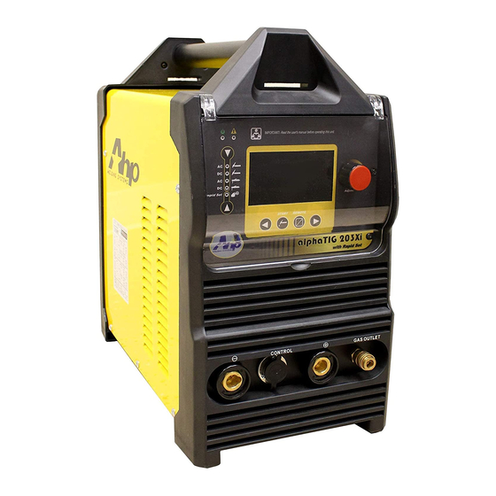
Page 9: About The Alpha Tig 203Xi
TO REQUEST A LIST OF AUTHORIZED DEALERS. All new AHP welders, shall be warrantied to the original owner for a The AlphaTIG 203Xi is the latest and most advanced edition of the period to extend for 3 years from date of purchase against breakage, long-running AHP AlphaTIG series. -
Page 10: Specifications
203Xi Specifications and Need-to-Know Information Feature and Range AlphaTIG 203Xi Specifications Feature Range Start Type HF and Lift Start (Lift is initiated with switch or pedal only) Input/Output Operating Range Process AC/DC TIG and Stick Amp Control 2T/4T Switch Control Sequencer or Pedal Control... -
Page 11: Generator Operation Information
203Xi Specifications and Need-to-Know Information Generator Operation Information the lifespan of the unit. Routine overheating damage will usually leave signs that can be determined during warranty repair. Damage caused by intentional abuse of the duty cycle will not be covered un- This unit may be used with any clean power rated 240V der warranty. -
Page 12: Hf Point Gap Maintenance
203Xi Specifications and Need-to-Know Information cumstances should you attempt to modify or make unauthorized for this welder. If you have any issues or questions concerning point changes to the welder or its programming. To do so will void the war- gap adjustment, call or contact Ahp tech support before attempting ranty. -
Page 13: Tig Shielding Gas Information
203Xi Specifications and Need-to-Know Information TIG Shielding Gas Information refuse the gas, and insist on pure Argon, or find another store willing to sell 100% pure argon. (Medical grade purity is not necessary). Pure Argon is recommended for use in your Ahp TIG welder. This The regulator is a floating ball type. -
Page 14: Tig Polarity And Tungsten Type
203Xi Specifications and Need-to-Know Information TIG Polarity and Tungsten Type that are found in Lanthanated. Overall, however, Ceriated is a suitable Never Tungsten type for most inverter welder general applications. use pure tungsten (green band) or Zirconiated ( usually brown Selecting the correct TIG polarity of the connections is band). -
Page 15: Tungsten Preparation
203Xi Specifications and Need-to-Know Information Tungsten Preparation However, if you do not have one, you may use a bench grinder with a fine grit stone that is dedicated to grinding Tungsten only. Proper Tungsten electrode preparation is important to arc stability... - Page 16 203Xi Specifications and Need-to-Know Information penetration. However, in certain conditions, if the work piece be- but especially for E6011 with this machine. For general purpose fab- comes magnetized, or some part of the welding table does, then the rication, and practical use, consider using E7014. This is considered a arc may become highly unstable while welding in DCEP.
-
Page 17: Front Panel Features
203Xi Component Identification and Explanation of Function Front Panel Features electrode holder. The stick torch should remain in the positive while welding in AC as well. In TIG mode this is always the loca- tion of the work clamp. - Page 18 203Xi Component Identification and Explanation of Function This unit uses a reliable high output fan mounted in the rear tion. There is no neutral in a welder circuit. Do not change, length- NOTICE: of the unit (not pictured). It pulls cooler air in from the rear and push- en, or otherwise alter the input cable or plug.
-
Page 19: Control Panel Features
203Xi Component Identification and Explanation of Function Control Panel Features NOTICE: Because of the limited output of the unit while operating on 120V, while Rapid The control panel layout below works in conjunction with the display. Set is turned on, some limits are placed on selecting a Stick electrode type and Some buttons perform a different function based on the mode they are size as well as material thickness in both TIG and Stick modes. - Page 20 203Xi Component Identification and Explanation of Function Control Panel Features 6. Remote Operation Selector. This button allows the user to select between using the foot pedal, torch switch, or special torch with separate switch and amp control on the handle. For Foot Pedal use, or slider control mounted on the torch handle, select “Pedal”. For torch switch mode, select between 2T and 4T operation. For special torch with separate switch and amp control select both pedal and 2T, or pedal and 4T.
-
Page 21: Lcd Screen Features
203Xi Component Identification and Explanation of Function NOTICE: The LCD Screen depicted below is shown with all features displaying at the same time, in order to give a full picture of how the screen works. However, all of the segments and features will never be on at the same time (except during the boot cycle). - Page 22 203Xi Component Identification and Explanation of Function LCD Screen Features 6. Material Thickness Indicator. When Rapid Set is selected for either TIG or Stick, this area will appear and become active. Select the approximate material thickness that is being welded with the right arrow (#14) parameter selector button.
-
Page 23: Using Ac Controls In Tig Welding
203Xi Component Identification and Explanation of Function Using AC Controls in TIG Welding balance control on this unit as a tool that can be used to divide the AC weld cycle from 20% electrode positive all the way up to 80% electrode positive. -
Page 24: Using 2T/4T/Pedal Functions
203Xi Component Identification and Explanation of Function nice broad range that balances arc cone width, tungsten life, and noise 30% Positive 50% Positive levels without presenting problems associated with either extremely low AC frequency or extremely high AC frequency. -
Page 25: Pulse Use And Operation
203Xi Component Identification and Explanation of Function 2T operation is the simplest way of welding. It is a simple “press and perage may be varied throughout the range from minimum to the hold” function to operate the weld cycle. When you press and hold the maximum Amperage set on the panel. -
Page 26: Starting The Tig Arc
203Xi Component Identification and Explanation of Function per second that occur. Pulse frequency controls the arc constriction ished) the arc will jump from the Tungsten tip directly to the metal. and also helps with heat management. The slow pulse frequency of 1 The High Frequency start is preferred while welding on Aluminum hertz gives a “stacked”... -
Page 27: Welding In Stick Mode
203Xi Component Identification and Explanation of Function slightly sticking to the work piece. It is best performed with low DC welding. It is not designed for E6010 and some other types of cellu- start Amp values, 20 Amps or less. In AC, Lift start may be also per- lose based flux rods. -
Page 28: Useful Tig Settings
203Xi Component Identification and Explanation of Function Useful TIG Settings Pulse Amps: 50– 75% of Welding Amps Pulse Frequency: 1.5 to 3 Hz for appearance; 100 to 200 Hz for Heat control. It is very hard to recommend a welding setting that is good for all... -
Page 29: Series Air-Cooled Tig Torch Information
203Xi Component Identification and Explanation of Function 26 Series Air-Cooled Welding Torch (Typical Type) Parts and Assembly. Typical Everlast and NOVA Torch Assembly (17,18, 26 Series) (Some parts may not appear exactly the same but are equal in assembly order and type.) Tungsten not included. - Page 30 203Xi Component Identification and Explanation of Function 7 PIN CONNECTOR Bridge a Jumper to Pin 7 To Pedal or Torch Switch ON/OFF Bridge a Jumper to Pin 6 To Pedal or Torch Switch ON/OFF High Middle Potentiometer (VR)
-
Page 31: Troubleshooting
203Xi Troubleshooting Trouble/Description Possible Cause Solution Unit will not turn on. No lights on panel. Unit Not plugged in. Bad Outlet Main Breaker tripped. Investigate cause and remedy. If switch is suspected contact Ahp. Check sim- Faulty welder switch.
Need help?
Do you have a question about the alphaTIG 203Xi and is the answer not in the manual?
Questions and answers
Turns on, yellow caution light on, after self test main switch trips and my 50 amp breaker in panel.
The yellow caution light turns on and the main switch trips on the AHP WELDS alphaTIG 203Xi due to a short circuit or overload. This indicates a severe problem or fault in the system. The main circuit breaker in the panel box may also trip. The power supply should be checked for proper wiring and grounding.
This answer is automatically generated