
Subscribe to Our Youtube Channel
Related Manuals for Thermo Electron 3950


Summary of Contents for Thermo Electron 3950
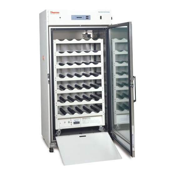
- Page 1 Models 3950 and 3951 29 cu. ft. Capacity Forma Reach-In CO Incubator Operating and Maintenance Manual Manual No: 7003950 Rev. 7...
- Page 2 Removed note about shipping tape on screws of sidewalls 20959/IN-3048 10/1/02 Added spacers to power supply mounting 20841/IN-3038 7/10/02 Updated 3950 electrical schematic from 285758 to 460038 GFI outlet 20883/IN-3034 6/12/02 Clarified p-trap alignment on page 1-3 20651/IN-3019 2/26/02 Updated 1900008-06-1 to rev. 5, chg in control panel mounting hardware ccs...
- Page 3 Model 3950/3951 _______________________________________________________________________________________ Important operating and/or maintenance instructions. Read the accompanying text carefully. Ce symbole attire l'attention de l'utilisateur sur des instructions importantes de fonctionnement et/ou d'entretien. Il peut être utilisé seul ou avec d'autres symboles de sécurité. Lire attentivement le texte d'accompagnement.
- Page 4 Model 3950/3951 _______________________________________________________________________________________...
-
Page 5: Table Of Contents
Model 3950/3951 _______________________________________________________________________________________ Table of Contents Section 6 - Factory Options ......6 - 1 Section 1 - Installation and Start-Up ....1 - 1 6.1 Connections to External Equipment . -
Page 6: Section 1 - Installation And Start-Up
Model 3950/3951 ____________________________________________________________________Installation and Start-Up Section 1 - Installation and Start-Up Figure 1-2 Back View Figure 1-1 Front View Figure 1-3 Side View 1 - 1... -
Page 7: Control Panel Keys, Displays And Indicators
Model 3950/3951 ____________________________________________________________________Installation and Start-Up 1.1 Control Panel Keys, Displays and Indicators 1.2 Operation of the Keypad The Model 3950 Series Reach-In Incubator has four basic modes that allow incubator setup: Run, Setpoints, Calibration and System Configuration. • Run is the default mode during normal operation. -
Page 8: Installing The Unit
Model 3950/3951 ____________________________________________________________________Installation and Start-Up 1.3 Installing the Unit c. Installing the Shelves The shelves may be a. Choosing the Location installed at any level in the incubator. Install a shelf channel on each Units must be installed against a wall or similar side. -
Page 9: The Water Supply
With the water The 3950 Series also has an internal outlet located on the turned on, a float valve inside the incubator regulates the water right side of the interior back wall. The outlet is to provide level in the humidity reservoir. -
Page 10: Connecting The Co Gas Supply
Model 3950/3951 ____________________________________________________________________Installation and Start-Up The CO gas supply being connected should be industrial Connecting the CO Gas Supply grade 99.5% pure and should not contain siphon tubes. Install a two-stage pressure regulator at the cylinder outlet. The high pressure gauge at the tank should have 0-2000 psig range. The... -
Page 11: Setting The Overtemp Setpoint
Run mode, or press the right/left arrow keys to go to next/previous parameter. All Model 3950 Series incubators are equipped with a sec- ondary temperature monitoring system to monitor the air tem- perature inside the cabinet. This system is designed as a safety device to turn off all heaters in the event of a temperature con- trol failure. - Page 12 Model 3950/3951 ____________________________________________________________________Installation and Start-Up 1 - 7...
-
Page 13: Section 2 - Calibration
Section 2 - Calibration b. Calibrating the CO System 2.1 Calibration Mode Model 3950 Series incubators have a CO sensor. The incu- bator atmosphere is not only effected by the quantity of CO After the unit has stabilized, several different systems can present but also by the air temperature and water vapor present be calibrated. - Page 14 Model 3950/3951 _____________________________________________________________________________Calibration 2 - 2...
-
Page 15: Section 3 - Configuration
Model 3950/3951 _____________________________________________________________________________Configuration c. Setting an Access Code Section 3 - Configuration A 3-digit Access Code can be entered to avoid unautho- 3.1 Configuration Mode rized personnel from changing the setpoints, calibration, or con- figuration. A setting of 000 will bypass the access code. The Several features available in the Configuration Mode allow factory setting is 000. -
Page 16: Enabling Temp Alarms To Trip Relay Contacts
Model 3950/3951 _____________________________________________________________________________Configuration i. Setting New Zero Number for New CO Sensors f. Setting Low CO Alarm Limit (tracking alarm) If a new CO sensor is being installed, the two numbers on The low CO alarm limit is the deviation from the CO... -
Page 17: Selecting A Primary Tank W/ Gas Guard Option
Model 3950/3951 _____________________________________________________________________________Configuration l. Selecting a Primary Tank w/ Gas Guard Option On units equipped with the Gas Guard option, a primary tank can be selected. The primary tank will be either Tank 1 or 2. The factory setting is Tank 1 . - Page 18 Model 3950/3951 _____________________________________________________________________________Configuration 3 - 4...
- Page 19 Model 3950/3951 _____________________________________________________________________________Configuration 3 - 5...
-
Page 20: Section 4 - Alarms
4.1 Alarms The microprocessor in 3950 Series incubators continually The Model 3950 Series incubator is equipped with a sys- scans all available sensors to ensure that they are operating tem which notifies the user of an alarm condition inside the properly. - Page 21 PREVENTIVE MAINTENANCE Incubators Your equipment has been thoroughly tested and calibrated before shipment. Regular preventive maintenance is important to keep your unit functioning properly. The operator should perform routine cleaning and maintenance on a regular basis. For maximum performance and efficiency, it is recommended the unit be checked and calibrated periodically by a qualified service technician. The following is a condensed list of preventive maintenance requirements.
- Page 22 Incubators ______________________________________________________________________________ Preventive Maintenance Preventive Maintenance for 3950 Series Incubators Refer to Action Daily Weekly Yearly Manual Section 1.4ie Check CO tank levels. Check CO and temperature display versus setpoints Inspect door latch, hinges and door gasket seal. * Verify and document CO and temperature calibration 1.4b, 5.3...
-
Page 23: Section 5: Maintenance
Model 3950/3951 _____________________________________________________________________________Maintenance Some precautions in the cleaning and care of the incubator Section 5: Maintenance glass doors: Moisture leaches alkaline materials (sodium, Na) from the surface of the glass. Evaporation of the moisture concentrates If the unit has been in service, turn it... -
Page 24: Replacing The Power Fuses
Model 3950/3951 _____________________________________________________________________________Maintenance 5.4 Replacing the Power Fuses De-energize all potential sources of energy to this unit and lockout/tagout their controls. (O.S.H.A. Regulation, Section 1910- 147.) High voltage is present behind control panel. The remote overtemp alarm system should be installed only by qualified electrical service per- sonnel. -
Page 25: Section 6 - Factory Options
Model 3950/3951 __________________________________________________________________________Factory Options Section 6 - Factory Options black to additional 1535 to additional 1535 modules modules 6.1 Connections to External Equipment (2) orange wires (1) red wire (1) green wire a. Connecting the Remote Alarm Contacts (3) yellow wires... -
Page 26: Gas Guard
Model 3950/3951 __________________________________________________________________________Factory Options The 3950 Series incubators can be equipped with a built-in Gas Guard system that will operate with a CO gas supply. The Accuracy of the output at the board terminal strip Gas Guard uses two pressure switches to continuously monitor to the incubator display is ±1 unit. -
Page 27: Inner Doors
Model 3950/3951 ____________________________________________________________________________Specifications Section 7 – Specifications Audible and visual alarms occur on the control panel when 7.1 Specifications* the gas guard switches from one supply to the other. The audi- ble alarm sounds until the operator presses the Silence key on * Specifications are based on nominal voltages of 115V or 230V the control panel. - Page 28 230W max, 0.5 mA leakage current 190544 0-1 volt output board, FI Remote Alarm Contacts: Deviation of temperature, & power. N/O & N/C Certification: 3950 Series - UL, CSA, CE Unit BTU Output 3951 Series – CSA, CE 115V/230V: 510 BTUH (150W) Safety Specifications: Altitude:...
-
Page 29: Section 8 - Spare Parts
For example, in CAT II which is the catego- 230135 1 amp fuse (3950 accessory outlet) ry used for instruments in installations supplied from a supply compa- rable to public mains such as hospital and research laboratories and 230158 2.5 amp fuse (3950 interior outlet) - Page 39 Model 3950/3951 ______________________________________________________________________Electrical Schematics 9 - 1...
- Page 40 Model 3950/3951 ______________________________________________________________________Electrical Schematics 9 - 2...
- Page 41 Model 3950/3951 ______________________________________________________________________Electrical Schematics 9 - 3...
- Page 42 Model 3950/3951 ______________________________________________________________________Electrical Schematics 9 - 4...
- Page 43 Thermo Electron Corporation Controlled Environment Equipment Millcreek Road, P.O. Box 649 Marietta, Ohio 45750 U.S.A. Telephone (740) 373-4763 Telefax (740) 373-4189...
Need help?
Do you have a question about the 3950 and is the answer not in the manual?
Questions and answers