
Related Manuals for Thermo Electron iEMS


Summary of Contents for Thermo Electron iEMS
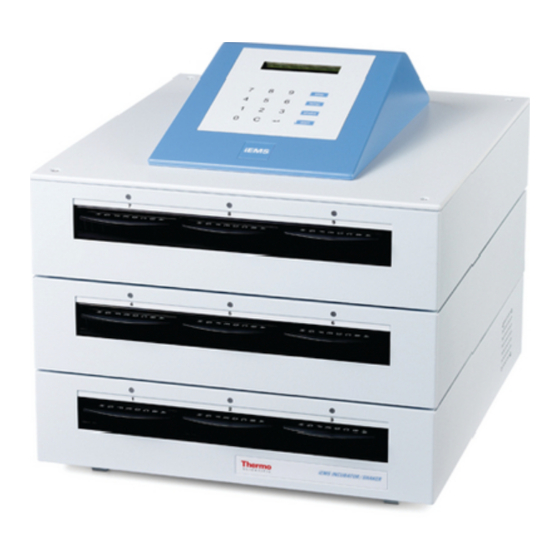
- Page 1 iEMS Incubator / Shaker iEMS Incubator / Shaker User Manual Rev. 3.0, Cat. no. 1506200A...
- Page 2 All other trademarks and registered trademarks are the property of their respective holders. Disclaimer Thermo Electron reserves the right to change its products and services at any time to incorporate technological developments. This manual is subject to change without prior notice as part of a continuous product development.
-
Page 3: Table Of Contents
Warranty Certificate ..................... 50 Index ..........................51 Glossary and Abbreviations ..................54 Appendix A: iEMS Incubator / Shaker Quick Reference Guide ............55 Appendix B: Certificate of Decontamination ................... 56 Appendix C: iEMS Incubator / Shaker Feedback Form..............57 Appendix D: Addresses ........................58 Notes .......................... - Page 4 Introduction to the iEMS Incubator / Shaker............... 9 Intended use ........................9 Principle of operation...................... 9 Advantages of using iEMS Incubator / Shaker .............. 9 Functional Description ....................10 iEMS Incubator / Shaker front view................10 iEMS Incubator / Shaker rear view ................11 Keyboard and display ....................
- Page 5 Glossary and Abbreviations ..................54 13.1 Keywords for web pages ....................54 Appendix A: iEMS Incubator / Shaker Quick Reference Guide ............55 Appendix B: Certificate of Decontamination ................... 56 Appendix C: iEMS Incubator / Shaker Feedback Form..............57 Appendix D: Addresses ........................58 Notes ..........................
- Page 6 List of Figures and List of Tables List of Figures Fig. 4.1 iEMS Incubator/Shaker front view ............... 10 Fig. 4.2 iEMS Incubator/Shaker rear view ................ 11 Fig. 4.3 iEMS Incubator/Shaker keyboard ................ 12 Fig. 4.4 iEMS Incubator/Shaker display ................12 Fig.
-
Page 7: Safety Symbols And Markings
1 Safety Symbols and Markings These symbols are intended to draw your attention to particularly important information and alert you to the presence of hazards as indicated. Safety symbols and markings used on the iEMS Incubator/Shaker Power ON Power OFF... -
Page 8: About The User Manual
Troubleshoot the instrument performance • Maintain the instrument This User Manual also describes features and specifications of the iEMS Incubator/Shaker hardware and on-board software. Chapter 6 Operation explains the operating procedures. The user should be familiar with the contents of Chapter 7 on maintenance. -
Page 9: Introduction To The Iems Incubator / Shaker
Chapter 3: Introduction to the iEMS Incubator / Shaker 3 Introduction to the iEMS Incubator / Shaker The iEMS Incubator/Shaker consists of three modules, each module having a capacity of three (3) microplates at a time. 3.1 Intended use The iEMS Incubator/Shaker is a high-quality stand-alone microplate incubator and orbital shaker intended for laboratory research use by professional personnel. -
Page 10: Functional Description
All slot positions within a module are shaken simultaneously. Each slot of the iEMS Incubator/Shaker has a control LED (light-emitting diode) that displays the status of the slot. The LED will change to a specific color based on the status of the slot. -
Page 11: Iems Incubator / Shaker Rear View
Chapter 4: Functional Description iEMS Incubator / Shaker rear view Cooling-air inlet DIP switches (not in use) Device link RS-485 (not in use) Computer RS-232C/device link RS-485 (not in use) Cooling-air outlet Instrument label Fig. 4.2 iEMS Incubator/Shaker rear view ... -
Page 12: Keyboard And Display
Chapter 4: Functional Description Keyboard and display Fig. 4.3 iEMS Incubator/Shaker keyboard Listed below are the functions of the keyboard keys: stop Stops the ongoing operation. temp Sets the incubation temperature ON or OFF. Used for starting preincubation (preheating) of the thermal microplate holders to the temperature set in processing protocol parameters. -
Page 13: Thermal Microplate Holder
The thermal microplate holder is designed for holding the microplate during the incubation process, ensuring accurate temperature control. Note: Adjust the screws (Fig. 4.5, item 4) with a screwdriver so that the microplate is held firmly in place during shaking. iEMS Incubator/Shaker User Manual Rev. 3.0, Cat. no. 1506200A... -
Page 14: Installation
5.2 What to do upon delivery 5.2.1 How to unpack Move the unpacked instrument to its site of operation. Unpack the iEMS Incubator/Shaker instrument and accessories carefully with the arrows on the transport package pointing upwards. The following notes and instructions are... -
Page 15: Checking Delivery For Completeness
If any parts are damaged, contact your local Thermo representative. 5.2.4 Climatic requirements When you set up your iEMS Incubator/Shaker, avoid sites of operation with excess dust, vibrations, strong magnetic fields, direct sunlight, draft, excessive moisture or large temperature fluctuations. -
Page 16: Things To Avoid
Chapter 5: Installation 5.2.5 Things to avoid Do not smoke, eat or drink while using the iEMS Incubator/Shaker. Wash your hands thoroughly after handling test fluids. Observe normal laboratory procedures for handling potentially dangerous samples. Use proper protective clothing. Use disposable gloves. Ensure that the working area is well ventilated. -
Page 17: Mains Supply Cable
2. Connect the mains supply cable to the mains input socket (Fig. 4.1, item 6) at the back of the left side panel. 3. Connect the instrument to a correctly installed line power outlet that has a protective conductor that is grounded. iEMS Incubator/Shaker User Manual Rev. 3.0, Cat. no. 1506200A... -
Page 18: Setup
3. Program the new time (hh mm ss) and press (24-hour clock). The baud rate is used for service purposes only. stop If you want to interrupt the setup, press to return to the READY state. iEMS Incubator/Shaker User Manual Rev. 3.0, Cat. no. 1506200A... -
Page 19: Operation
↵ (Enter) start start start Protocol Set protocol HEAT ON SHAKING starts parameters, see 6.2 READY READY READY READY Fig. 6.1 Principle of operation iEMS Incubator/Shaker User Manual Rev. 3.0, Cat. no. 1506200A... -
Page 20: Programming Protocols
For example, TEMPERATURE 30.0ºC 30 ↵ Press INC TIME 00:00:00 Note: stop If you want to interrupt the programming, press to return to the READY state. Your changes will be saved. iEMS Incubator/Shaker User Manual Rev. 3.0, Cat. no. 1506200A... - Page 21 The value will be entered at the location of the cursor. For example, for an interval shaking time of zero: SHAKE TIME 00:00:20 00 00 ↵ Press (Enter) INT TIME 00:00:00 iEMS Incubator/Shaker User Manual Rev. 3.0, Cat. no. 1506200A...
-
Page 22: Table 6.1 Speed Settings Of The Shaker
If you try to start a slot with a protocol PLACE 2 with shaking, an error message will PROHIBITED OPERATION appear on the display: On the display, the READY state will READY 09:26:15 appear after the programming phase. iEMS Incubator/Shaker User Manual Rev. 3.0, Cat. no. 1506200A... -
Page 23: Slot Status - Control Leds And Audio Signal
Chapter 6: Operation Slot status – control LEDs and audio signal Each slot of the iEMS Incubator/Shaker has a control LED (light-emitting diode) that displays the status of the slot. The LED will change to a specific color based on the status of the slot. An audio signal is given when the green LED is turned on (see Section 6.4.3.6). -
Page 24: Normal Operation
The covers of the thermal microplate holders are not spring-loaded, but you should take care not to trap your fingers when closing the cover of the holder. Avoid bumping the microplate holder while inserting it into the slot. iEMS Incubator/Shaker User Manual Rev. 3.0, Cat. no. 1506200A... -
Page 25: Fig. 6.3 Inserting The Thermal Microplate Holder Into A Slot
Pushing down the microplate holder to latch it properly Note: If the thermal microplate holder is not latched into position, it may lose contact with the temperature controlling connectors at the rear of the slot. iEMS Incubator/Shaker User Manual Rev. 3.0, Cat. no. 1506200A... -
Page 26: Before Pressing Start
To minimize the likelihood of this occurring, it is recommended that you program all processing protocols within a module with the same shaking speed. iEMS Incubator/Shaker User Manual Rev. 3.0, Cat. no. 1506200A... -
Page 27: Operation
For example, if there is a protocol in progress with speed 5 and the adjoining slot is started with speed 3, all slots within the module will shake at speed 3. iEMS Incubator/Shaker User Manual Rev. 3.0, Cat. no. 1506200A... -
Page 28: Checking The Operation Stop Time
LED are turned off and the heating of the slot is turned off. 3. Re-insert the microplate holder into the slot. The orange LED is turned on and the heating of the slot turns back on. iEMS Incubator/Shaker User Manual Rev. 3.0, Cat. no. 1506200A... -
Page 29: Removing The Microplate
(Fig. 6.6). Be careful not to spill the contents of the microplate when you take the microplate holder out of the slot and when you remove the microplate from the holder. iEMS Incubator/Shaker User Manual Rev. 3.0, Cat. no. 1506200A... -
Page 30: Fig. 6.5 Removing The Microplate Holder - Lifting The Handle
Removing the microplate holder – lifting the handle Fig. 6.6 Removing the microplate holder – pulling the holder out 3. Place the microplate holder on a heat resistant surface. Open the cover and remove the microplate. iEMS Incubator/Shaker User Manual Rev. 3.0, Cat. no. 1506200A... -
Page 31: Preheating And Heating
0 Press to display the heating status of all slots. PLACES 1-9 If the heating is ON in every slot, the display will show: HEAT ON iEMS Incubator/Shaker User Manual Rev. 3.0, Cat. no. 1506200A... - Page 32 At this point, press to turn the heating ON in all slots, or press turn the heating OFF in all slots. READY 09:29:10 Press to return to the READY state. iEMS Incubator/Shaker User Manual Rev. 3.0, Cat. no. 1506200A...
-
Page 33: Shaking
The protocol stops, the LED turns to green, and you will hear a beeping sound. Press to return to the READY state if READY 09:29:15 you do not need to start a shake. iEMS Incubator/Shaker User Manual Rev. 3.0, Cat. no. 1506200A... -
Page 34: Verifying Incubation And Shaking Parameters
You can only view programmed incubation and shaking parameters of a slot while the slot is not heating or shaking. When you review the parameters, ensure that you do not make any unintentional changes to the programmed values. iEMS Incubator/Shaker User Manual Rev. 3.0, Cat. no. 1506200A... -
Page 35: Maintenance
Clean and decontaminate the surfaces if necessary. Although the iEMS Incubator/Shaker is constructed from high-quality materials, you must immediately wipe away spilled saline solutions, solvents, acids or alkaline solutions from outer surfaces to prevent damage, and wipe with deionized distilled aqua. -
Page 36: How To Replace Fuses
4. Place the fuse holder back into the slot and push it in until you hear a click. 5. Connect the power cable to the instrument and switch it ON. iEMS Incubator/Shaker User Manual Rev. 3.0, Cat. no. 1506200A... -
Page 37: Disposal Of Materials
EIA tests in a negative way resulting in bad test results. Warning: Always use disposable gloves and protective clothing and operate in a well-ventilated area. iEMS Incubator/Shaker User Manual Rev. 3.0, Cat. no. 1506200A... -
Page 38: How To Decontaminate The Instrument Surface
11 No. 14. Villanova, Pa.: NCCLS; 1991. Ref. National Committee for Clinical Laboratory Standards. Protection of Laboratory Workers from Instrument Biohazards; Proposed Guideline. NCCLS Document I17-P, Vol. 11 No. 15. Villanova, Pa.: NCCLS; 1991. iEMS Incubator/Shaker User Manual Rev. 3.0, Cat. no. 1506200A... -
Page 39: How To Pack For Service
The proposals for the procedures vary by country. Regarding the original packaging and packing materials, use the recycling operators known to you. For further information, contact your local Thermo representative. iEMS Incubator/Shaker User Manual Rev. 3.0, Cat. no. 1506200A... -
Page 40: Troubleshooting Guide
Do not touch or loosen any screws or parts other than those specially designated in the instructions. Doing so might cause misalignment and will invalidate the instrument warranty. iEMS Incubator/Shaker User Manual Rev. 3.0, Cat. no. 1506200A... -
Page 41: General
Refer to Section 6.4.3.6. During shaking Do not place the microplate holder in or remove it from the instrument while the instrument is shaking. This may damage the shaking mechanism. iEMS Incubator/Shaker User Manual Rev. 3.0, Cat. no. 1506200A... -
Page 42: Temperature
Refer to Sections 6.2 and 6.4.3.3. During shaking Do not place the microplate holder in or remove it from the instrument while the instrument is shaking. This may damage the shaking mechanism. iEMS Incubator/Shaker User Manual Rev. 3.0, Cat. no. 1506200A... -
Page 43: Operation
If local or laboratory regulations prescribe regular decontamination, it is not advisable to use formaldehyde, since even small traces of formaldehyde affect the enzyme being used in EIA tests in a negative way resulting in bad test results. iEMS Incubator/Shaker User Manual Rev. 3.0, Cat. no. 1506200A... -
Page 44: Service Request Protocol
Decontaminate the instrument prior to disposal. See Section 7.4 and Appendix B on decontamination. 8.3 Service request protocol If the iEMS Incubator/Shaker requires service, contact your local Thermo representative or Thermo’s service department. Do not under any circumstances send the instrument for service without any prior contact. It is imperative to indicate the fault and nature of the required service. -
Page 45: Technical Specifications
Microplate dimensions Maximum 86 mm (W) x 128 mm (L) x 15 mm (H) Device interfaces 1. Serial RS-232C interface for computer 2. Serial RS-485 interface for other device link iEMS Incubator/Shaker User Manual Rev. 3.0, Cat. no. 1506200A... -
Page 46: Incubator Specifications
Orbit 1 mm (radius 0.5 mm) Programmable shaking time Up to 48 hours in steps of 1 second Programmable interval time Up to 48 hours in steps of 1 second iEMS Incubator/Shaker User Manual Rev. 3.0, Cat. no. 1506200A... -
Page 47: Safety Specifications
Chapter 10: Device Interfaces 9.4 Safety specifications The iEMS Incubator/Shaker fulfills the following requirements: EN 61010-1:1993 + A2:1995/IEC 61010-1:1990 + A1:1992 + A2:1995 including CENELEC Common Modifications, US and CA National differences EN 61010-2-010:1994 + A1:1996 including CENELEC Common Modifications, US and CA National... -
Page 48: In Conformity With The Requirements
100 – 120 Vac, 200 – 240 Vac 50/60 Hz, 380 VA max. CE mark CSA monogram UL mark iEMS Incubator/Shaker conforms to the following requirements: 73/23/EEC (Low Voltage Directive) 89/336/EEC (Electromagnetic Compatibility Directive, EMC) FCC Part 15, Subpart B/Class B... -
Page 49: Ordering Information
10 Ordering Information Contact your local Thermo representative for ordering and service information. Code Instrument 5112200 iEMS Incubator/Shaker with nine (9) thermal microplate holders, 220 – 240 V 5112207 iEMS Incubator/Shaker with nine (9) thermal microplate holders, 100 – 120 V... -
Page 50: Warranty Certificate
Chapter 11: Warranty Certificate 11 Warranty Certificate Thermo Electron Microplate Instrumentation Business products are fully guaranteed against defective parts and materials, including defects caused by poor workmanship, for a period of twelve (12) months from the date of delivery. Thermo will repair or replace defective parts or materials during the term of warranty at no extra charge for materials and labor provided that the products were used and maintained in accordance with Thermo's instructions. -
Page 51: Index
Heating..............................31 Heating time ............................21 Holder ..............................13 Incubation temperature........................20 Incubation time............................. 21 Incubation time tracking........................41 Incubator slot preheating ....................... 26, 40 Inserting the microplate ........................24 iEMS Incubator/Shaker User Manual Rev. 3.0, Cat. no. 1506200A... - Page 52 ..........................21 interval time ............................21 same for all slots..........................20 setting..............................20 shaking time ............................21 viewing .............................. 34 Placing the microplate into thermal microplate holder ..............24 iEMS Incubator/Shaker User Manual Rev. 3.0, Cat. no. 1506200A...
- Page 53 Transport damage ..........................15 Transport package.......................... 14, 15 Unpacking ............................. 14 Viewing parameters ........................34, 41 Voltage selector............................ 16 Warranty ............................14, 50 Weight............................. 16, 45 Working area ............................15 iEMS Incubator/Shaker User Manual Rev. 3.0, Cat. no. 1506200A...
-
Page 54: Glossary And Abbreviations
Incubator shaker shaker liquid handling shaking microplate solid phase assay(s) microplate incubator Thermo Thermo Electron iEMS Incubator/Shaker User Manual Rev. 3.0, Cat. no. 1506200A... -
Page 55: Appendix A: Iems Incubator / Shaker Quick Reference Guide
Appendix A: iEMS Incubator / Shaker Quick Reference Guide Appendix A: iEMS Incubator / Shaker Quick Reference Guide 1. Place the microplate into the thermal microplate holder so that well A1 is located in the upper left corner when viewed with the numbers on the holder's handle the right side up. -
Page 56: Appendix B: Certificate Of Decontamination
The decontamination procedure is required prior to shipping the instrument to Thermo Electron Oy, e.g., for repair. If, for any reason, the instrument is shipped back to Thermo Electron Oy, it must be accompanied by a dated and signed Certificate of Decontamination, which must be attached to the outside of the package containing the instrument. -
Page 57: Appendix C: Iems Incubator / Shaker Feedback Form
Appendix C: iEMS Incubator / Shaker Feedback Form Please send to Thermo Electron Oy Fax: +358-9-32910415 Appendix C: iEMS Incubator / Shaker Feedback Form Cat. no. Serial no. PURCHASED BY PURCHASED FROM Company/Organization Distributor Department Address Address Tel. Tel. Date of delivery... -
Page 58: Appendix D: Addresses
For the latest information on products and services, visit our worldwide web sites on the Internet at: http://www.thermo.com Manufactured by: Distributed by: P.O. Box 100, FIN-01621 Vantaa, Finland Tel. +358-9-329 100, Fax +358-9-3291 0415 www.thermo.com iEMS Incubator/Shaker User Manual Rev. 3.0, Cat. no. 1506200A... -
Page 59: Notes
iEMS Incubator/Shaker User Manual Rev. 3.0, Cat. no. 1506200A... - Page 60 iEMS Incubator/Shaker User Manual Rev. 3.0, Cat. no. 1506200A...
- Page 61 iEMS Incubator/Shaker User Manual Rev. 3.0, Cat. no. 1506200A...
Need help?
Do you have a question about the iEMS and is the answer not in the manual?
Questions and answers