
Subscribe to Our Youtube Channel
Related Manuals for Motorline professional MC50


Summary of Contents for Motorline professional MC50
- Page 1 MC50 MC50 USER/INSTALLER MANUAL v1.1 REV. 04/2022 Compatible hardware versions: 27042021 | 24092021...
-
Page 2: Table Of Contents
00. CONTENT INDEX 01. SAFETY INSTRUCTIONS 07. TROUBLESHOOTING INSTRUCTIONS FOR FINAL CONSUMERS/TECHNICIANS STANDARDS TO FOLLOW 08. CONNECTION SCHEME 02. CONTROL BOARD CONNECTIONS MAP - SLIDING GATES TECHNICAL SPECIFICATIONS CONNECTIONS MAP - SECTIONAL DOORS PROGRAMMING PRE-RECOMENDATIONS CONNECTIONS MAP - BARRIERS ESSENTIAL STEPS FOR INSTALLATION REMOTE CONTROLS "P"... -
Page 3: Safety Instructions
01. SAFETY INSTRUCTIONS ATENÇÃO: GENERAL WARNINGS This product is certified in accordance with European • This manual contains very important safety and usage information. Community (EC) safety standards. very important. Read all instructions carefully before beginning the installation/usage procedures and keep this manual in a safe place that This product complies with Directive 2011/65/EU of the it can be consulted whenever necessary. - Page 4 01. SAFETY INSTRUCTIONS 01. AVISOS DE SEGURANÇA WARNINGS FOR TECHNICIANS panel, must be provided on the product’s fixed power supply leads in accordance with the installation rules. • Before beginning the installation procedures, make sure that you have • If the product to be installed requires power supply of 230Vac or 110Vac, all the devices and materials necessary to complete the installation of ensure that connection is to an electrical panel with ground connection.
-
Page 5: Control Board
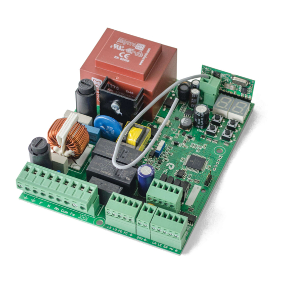
01. SAFETY INSTRUCTIONS 02. CONTROL BOARD TECHNICAL SPECIFICATIONS • Instructions in this manual are not followed. The MC50SC is a monophasic control board com a control system via incorporated rádio, developed for • Damaged is caused by unauthorized modifications the automation of sliding gates and sectional doors. •... -
Page 6: Programming Pre-Recomendations 5A
02. CONTROL BOARD 02. CONTROL BOARD PROGRAMMING PRE-RECOMENDATIONS PROGRAMMING PRE-RECOMENDATIONS To enhance knowledge about the control board operation, before proceeding to the setup, give special 01 • Auxiliary output for flashing light or 24V DC LED. attention to the instructions that follow. Open collector for the management of auxiliary functions: 02 •... -
Page 7: Remote Controls 6A
02. CONTROL BOARD 02. CONTROL BOARD REMOTE CONTROLS "P" MENU FUNCTIONS MAX. MIN. FACTORY Programming a remote control for full opening. MENU FUNCTION STATE PAGE PROGRAMMABLE VALUE Programming a remote control for pedestrian opening. SC: 03 BR: 04 Opening deceleration SE: 02 •... -
Page 8: E" Menu Functions 7A
02. CONTROL BOARD 03. PROGRAMMING "P" "E" MENU FUNCTIONS AUTOMATIC AND SEMI-AUTOMATIC COURSE PROGRAMMING • To access the E menu press the MENU key for 10sec. This menu allows automatic programming of the motor and deceleration. • Use ↓↑ to navigate through the menus. MENU •... -
Page 9: P1-Setting The Deceleration Time 8A
03. PROGRAMMING "P" 03. PROGRAMMING "P" AUTOMATIC AND SEMI-AUTOMATIC COURSE PROGRAMMING SETTING STRENGTH AND SENSITIVITY It allows you to adjust the motor sensitivity With this menu you can change the direction of the motor's movement, without change the Factory values in detecting obstacles. -
Page 10: P4-Pause Time 9A
03. PROGRAMMING "P" 03. PROGRAMMING "P" PAUSE TIME PHOTOCELLS PROGRAMMING 08 • Appears the function set from factory. If you want, change the it between 00 and 01 using ↓↑. Pause time adjustment of the total closur 09 • Press MENU for 1 seconds to confirm the defined function. Allows you to set the time that the gate will remain open. -
Page 11: P7-Operating Logic
03. PROGRAMMING "P" 03. PROGRAMMING "P" OPERATING LOGIC FLASHING LIGHT 01 • Press MENU for 3 seconds. This menu allows you to set the gate's operating mode. 02 • P0 appears. Press ↓ eight times. 03 • P8 appears. Press MENU for 1 second. Functioning in automatic mode 04 •... -
Page 12: Programming "E
03. PROGRAMMING "E" 03. PROGRAMMING "E" PRESENT MAN COURTESY LIGHT TIME This menu allows you to define the time (from 1 to 99 minutes) that the courtesy Deactivates present man light stays on after the gate completes the closing manoeuvre. Factory values This menu is only available if the Courtesy Light function is active in the P8 SC, BR, SE: 03... -
Page 13: E5-Electric Brake 12A
03. PROGRAMMING "E" 03. PROGRAMMING "E" ELECTRIC BRAKE RESET - RESTORE FACTORY VALUES 04 • Surge a função definida de fábrica. Se pretender, altere o valor entre 00 e 01, utilizando ↓↑. 01 • Press MENU for 6 seconds. 05 • Pressione MENU para guardar o valor definido. 02 •... -
Page 14: Components Test
06. COMPONENTS TEST CAPACITOR SCHEME To detect which components have problems during a sliding automatism installation, sometimes it's necessary to conduct tests with a direct connection to a 230V power supply. For this, it's necessary to interpose a capacitor on the connection so that the motor can work (check the capacitor type to be used in the product's manual). In the below diagram is shown how this connection must be made and how to merge the different component wires. -
Page 15: Troubleshooting
07. TROUBLESHOOTING INSTRUCTIONS FOR FINAL CONSUMERS/TECHNICIANS Anomaly Procedure Behavior Procedure II Discovering the origin of the problem 1 • Open control box and check if 3 • Switch off the control 4 • If the motor works, the 5 • If the motor doesn’t work, •... -
Page 16: Connection Scheme
08. CONNECTION SCHEME CONNECTIONS MAP - SLIDING GATES CLOSE OPEN... -
Page 17: Connections Map - Sectional Doors
08. CONNECTION SCHEME CONNECTIONS MAP - SECTIONAL DOORS Brown Black Black White Blue White White Verde Yellow Green Brown Blue Black... -
Page 18: Connections Map - Barriers
08. CONNECTION SCHEME CONNECTIONS MAP - BARRIERS See diagram on page 19 CLOSE OPEN...
Need help?
Do you have a question about the MC50 and is the answer not in the manual?
Questions and answers