
Related Manuals for Chord Electronics ULTIMA PRE 3


Summary of Contents for Chord Electronics ULTIMA PRE 3
- Page 1 Chord Electronics The Pumphouse, Farleigh Lane, East Farleigh, Kent, ME16 9NB. Great Britain. Product Communication | English +44 (0) 1622 721 444 info@chordelectronics.co.uk chordelectronics.co.uk ULTIMA PRE 3 Manual...
-
Page 2: Table Of Contents
Chord Electronics ULTIMA PRE 3 | Manual Contents 1.0 Safety 2.0 Warranty Introduction Warranty and registering Protection against liquids and heat Claims and exclusions Dismantling and radio frequency interference Connecting other equipment 3.0 Panels and remote control 4.0 Set up and installation... -
Page 3: Safety
Chord Electronics ULTIMA PRE 3 | Manual Safety Introduction Protection against liquids and heat Dismantling and radio frequency interference Connecting other equipment Safety 3 // 29... -
Page 4: Introduction
Chord Electronics Introduction Dismantling and radio ULTIMA PRE 3 | Manual Protection against liquids frequency interference and heat Connecting other equipment Introduction The ULTIMA PRE 3 is an advanced, ground- up design preamplifier built to complement ULTIMA amplification. It benefits from five inputs:... -
Page 5: Protection Against Liquids And Heat
Note: it is entirely normal for the If the ULTIMA PRE 3 comes into device to become warm contact with moisture or liquids, during use, particularly if immediately disconnect it from stacked. -
Page 6: Dismantling And Radio
3 or its power supply. Dangerous internal circuitry from radio voltages/currents exist within frequency interference. However, the ULTIMA PRE 3 and its power for optimal performance, it is supply, potentially posing a recommended that the following severe risk of electrocution and/ points are observed: or fire. -
Page 7: Connecting Other Equipment
Only disconnect when the respective manufacturer’s user ULTIMA PRE 3 is off. If the guide to confirm compatibility. power cable is disconnected during operation, there is a risk of damage to connected equipment. -
Page 8: Warranty
Chord Electronics ULTIMA PRE 3 | Manual Warranty Warranty and registering Claims and exclusions Warranty 8 // 29... -
Page 9: Warranty And Registering
ULTIMA PRE 3 | Manual Warranty and registering At the point of sale, Chord Use the form Electronics Ltd. provides below to record details. the ULTIMA PRE 3 with a Purchases should be comprehensive five-year registered at: warranty* that covers defects chordelectronics.co.uk/register- in materials and workmanship through fair wear and tear. -
Page 10: Claims And Exclusions
Chord Electronics Warranty and registering Claims and exclusions ULTIMA PRE 3 | Manual Claims and exclusions In the unlikely event of a claim, purchase details and the serial number will be needed in order to validate the warranty status and any possible repair/s. -
Page 11: Panels And Remote Control
Chord Electronics ULTIMA PRE 3 | Manual Panels and remote control Familiarisation The front panel The back panel The remote control Panels and remote control 11 // 29... -
Page 12: Familiarisation
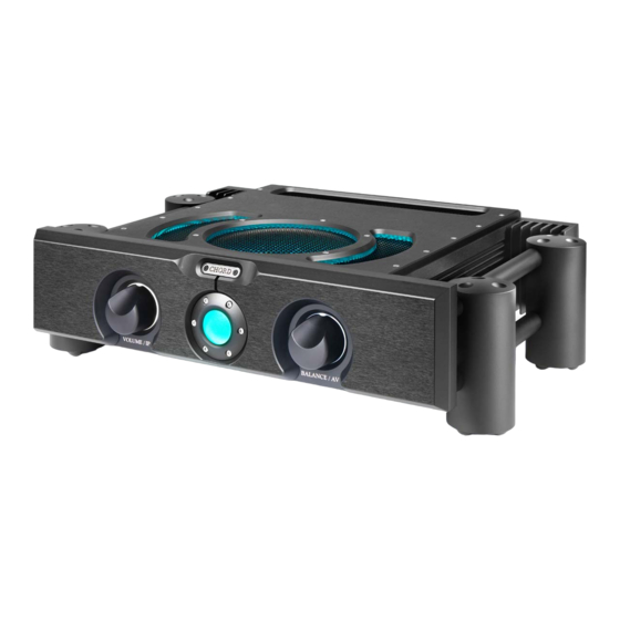
Familiarisation The back panel The front panel The remote control Familiarisation The ULTIMA PRE 3 is a five-input preamp with both balanced and unbalanced inputs and outputs. Its contemporary design makes it the ideal ‘hub’ for a Chord Electronics audio system. -
Page 13: The Front Panel
Familiarisation The back panel The front panel The remote control The front panel The front panel features the volume/input-selector control, power button and balance/AV bypass control. Volume control and Balance control and input selector AV bypass selector Power button 13 // 29... -
Page 14: The Rear Panel
Familiarisation The back panel The front panel The remote control The back panel The rear panel houses the device’s wide-ranging connectivity. Unbalanced RCA inputs A/V bypass inputs 3-5 input 5 V/3 A USB power output 10 A IEC AC power inlet with on/off rocker switch Balanced XLR and Balanced XLR inputs... -
Page 15: The Remote Control
The back panel The front panel The remote control The remote control The remote control offers control over the ULTIMA PRE 3, plus selected Chord Electronics devices. The top section is reserved for the BLU MKII CD digital transport, while the... -
Page 16: Set Up And Installation
Set up and installation Placement Connecting inputs Connecting to a power amplifier AV bypass Other rear panel connections Set up and installation 16 // 29... -
Page 17: Placement Connecting Inputs
Placement Connecting to a power Connecting inputs amplifier AV bypass Other rear panel connections Placement When positioning the device, allow a minimum of 15 cm all round for convection-cooling. Avoid placement inside cabinets etc. 17 // 29... - Page 18 Placement Connecting to a power Connecting inputs amplifier AV bypass Other rear panel connections Connecting to power and inputs Each input is arranged as a stereo Up to five source components pair, L (left top), R (right bottom). can be connected using balanced (XLR) and unbalanced (RCA) interconnects.
-
Page 19: Connecting To A Power Amplifier
Connecting inputs amplifier AV bypass Other rear panel connections Connecting to a power amplifier Using the XLR or RCA outputs shown in the illustration, connect the ULTIMA PRE 3 to the power amplifer’s corresponding inputs. XLR and outputs 19 // 29... -
Page 20: Av Bypass
Placement Connecting to a power Connecting inputs amplifier AV bypass Other rear panel connections AV bypass The AV bypass feature allows To connect the preamp to an AV WARNING: The volume control on the the output of an AV processor device using AV bypass: preamp will be bypassed, so check the... -
Page 21: Other Rear Panel Connections
Grounding post (device additional connections: a 5 V/ 3 earthing): A USB power output, 12 V trigger The ULTIMA Pre 3 can be used output and a grounding post. to ‘wake’ other units from (and In some European countries, hum... -
Page 22: Operation
Chord Electronics ULTIMA PRE 3 | Manual Operation Basic operation Volume and input select Balance and AV bypass Dimmable lighting Operation 22 // 29... -
Page 23: Basic Operation
The two-second boot-up sequence turns the power button from red to green. Once ready for playback, the power button will click and display teal. The ULTIMA PRE 3 can be used with the remote control or front panel. 23 // 29... -
Page 24: Volume And Input Select
Basic operation Balance and AV bypass Volume and input select Dimmable lighting Volume and input select The volume/IP control knob can Note: Ensure the volume is be used to adjust the volume and set to the mimimum level select between the preamp’s five (fully anticlockwise) before inputs. -
Page 25: Balance And Av Bypass
When position. Rotating the knob deselecting AV bypass mode, clockwise or anticlockwise will also ensure the ULTIMA PRE 3’s adjust the bias to the right or left volume control is either at the channels, respectively. minimum or at a low level before increasing to a comfortable level. -
Page 26: Dimmable Lighting
Chord Electronics Basic operation Balance and AV bypass ULTIMA PRE 3 | Manual Volume and input select Dimmable lighting Dimmable lighting The lighting level of the front panel and top panel LED ring can be dimmed using the remote control. Press ‘DIM’ to reduce the brightness, pressing again to restore. -
Page 27: Technical Specifications
Chord Electronics ULTIMA PRE 3 | Manual Technical specifications Technical specifications Technical specifications 27 // 29... -
Page 28: Technical Specifications
Chord Electronics Technical specifications ULTIMA PRE 3 | Manual Technical specifications Frequency response 10 Hz-200 kHz +/- 3 dB 0.002 % 20 Hz-20 kHz Signal to noise ratio -105 dB on all inputs Input impedance 100 kΩ Output impedance 560 Ω...
Need help?
Do you have a question about the ULTIMA PRE 3 and is the answer not in the manual?
Questions and answers