
Related Manuals for Yardworks 060-0550-6


Summary of Contents for Yardworks 060-0550-6
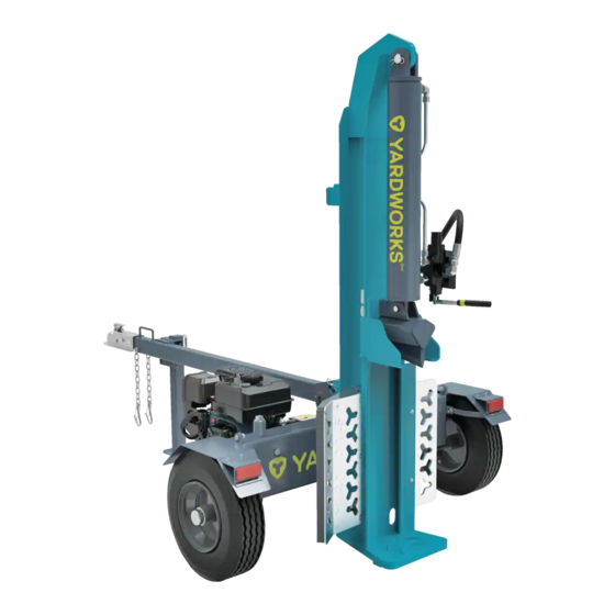
- Page 1 25 Ton Full Beam Log Splitter model number 060-0550-6 | contact us: 1.866.523.5218 IMPORTANT: Please read this manual carefully before operating this snowblower and save it for reference.
-
Page 2: Table Of Contents
TABLe OF CONTeNTS model no. | contact us: 1.866.523.5218 060-0550-6 TABLE OF CONTENTS SAFETY INSTRUCTIONS SPECIFICATIONS ASSEMBLY OPERATION MAINTENANCE STORAGE TROUBLESHOOTING WARRANTY For problems or questions, DO NOT ReTURN TO STORe. Please contact one of our Customer Service Agents who would be happy to assist you. -
Page 3: Safety Instructions
| contact us: 1.866.523.5218 060-0550-6 SAFeTy DeFINITIONS The purpose of safety symbols is to attract your attention to possible dangers. The safety symbols, and their explanations, deserve your careful attention and understanding. The safety warnings do not by themselves eliminate any danger. The instructions or warnings they give are not substitutes for proper accident prevention measures. - Page 4 | contact us: 1.866.523.5218 060-0550-6 DANGeR: Rotating parts can entangle hands, feet, hair, clothing and/or accessories. Traumatic amputation or severe laceration can result. Keep hands and feet away from rotating parts. Tie up long hair and remove jewelry.
- Page 5 | contact us: 1.866.523.5218 060-0550-6 WARNING: Keep Operator Work Zone Clear Keep work zone clear of debris while working to ensure safe footing. WARNING: Before removing the pin installed into the front support leg make sure hitch is installed onto vehicle.
- Page 6 | contact us: 1.866.523.5218 060-0550-6 CAUTION: Improper treatment or use of the log splitter can damage it, shorten its life and void your warranty. Use the log splitter only for intended uses. Operate only on level surfaces.
- Page 7 | contact us: 1.866.523.5218 060-0550-6 When starting the engine: DO NOT attempt to start a damaged engine. Make certain that the gasoline cap, air filter, spark plug, fuel lines and exhaust system are properly in place. Allow spilled gasoline to evaporate fully before attempting to start the engine.
- Page 8 | contact us: 1.866.523.5218 060-0550-6 TRAINING 1. Read the Operator’s Manual completely before attempting to use this log splitter. 2. Do not allow anyone to operate your log splitter who has not read the Operator’s Manual or has not been instructed on the safe use of the log splitter.
- Page 9 | contact us: 1.866.523.5218 060-0550-6 PRePARATION 1. Be thoroughly familiar with all controls and with proper use of the equipment. 2. Safety Gear: Always wear safety shoes or heavy boots when operating the machine. – Always wear safety glasses or goggles when operating the machine.
- Page 10 | contact us: 1.866.523.5218 060-0550-6 OPeRATION 1. Before starting this log splitter, review all safety rules. Failure to follow these rules may result in serious injury to the operator or bystanders. 2. Be sure to confirm all hose connections and hose clamps are tight before each use. It is possible for connections to vibrate loose over time.
- Page 11 | contact us: 1.866.523.5218 060-0550-6 MAINTeNANCe AND STORAGe 1. Always shut off the engine while repairing or adjusting the splitter except as recommended by the manufacturer. 2. Clean debris and chaff from the engine cylinder, cylinder head fins, recoil starter cover, and muffler areas.
- Page 12 | contact us: 1.866.523.5218 060-0550-6 SAFeTy AND DATAPLATe LABeLS These labels warn you of potential hazards that can cause serious injury. Read them carefully. If a label comes off or becomes hard to read, contact Technical Support Team for possible replacement.
- Page 13 This artwork belongs to Champion Power Equipment. The contents are confidential and privileged and shall not be disclosed to or used by or for outside parties without the explicit consent of Champion Power Equipment. MODEL 100876 MODÉLE CTC 060-0550-6 MANUFACTURE DATE XXXX DATE DE FABRICATION SERIAL NO.
- Page 14 | contact us: 1.866.523.5218 060-0550-6 SAFeTy SyMBOLS Some of the following symbols may be used on this product. Please study them and learn their meaning. Proper interpretation of these symbols will allow you to more safely operate the product.
- Page 15 | contact us: 1.866.523.5218 060-0550-6 Symbol Meaning Always keep feet away from the wedge and the ram. Moving parts can crush or cut. Hot Surface. To reduce the risk of injury or damage, avoid contact with any hot surface.
- Page 16 | contact us: 1.866.523.5218 060-0550-6 Symbol Meaning DO NOT exceed the maximum 45 MPH (72 KM/H) towing speed. Always check all local, state or provincial regulations regarding towing, licensing and lights before towing your log splitter. Review towing safety warnings in your towing vehicle manual.
- Page 17 | contact us: 1.866.523.5218 060-0550-6 QUICKSTART LABeL SyMBOLS Some of the following symbols may be used on this product. Please study them and learn their meaning. Proper interpretation of these symbols will allow you to more safely operate the product.
-
Page 18: Specifications
| contact us: 1.866.523.5218 | contact us: 1.866.523.5218 060-0550-6 060-0550-6 LOG SPLITTeR Ram Force 25 Ton Cycle Time 11 seconds Hydraulic Tank Capacity 4 gal (15.1 L) Total Hydraulic Oil System Capacity 4.5 gal (17 L) Max Log Length 24 in. - Page 19 | contact us: 1.866.523.5218 060-0550-6 HyDRAULIC OIL SySTeM Capacity 4.5 gal (17 L) For year round use in warmer climates (always ABOVE 0˚C / 32˚F): ISO 32/SAE10W – Universal Hydraulic Oil – For year round use in colder climates (BELOW 0˚C / 32˚F): Automatic Transmission Fluid –...
- Page 20 | contact us: 1.866.523.5218 060-0550-6 IMPORTANT MeSSAGe ABOUT TeMPeRATURe Your product is designed and rated for continuous operation at ambient temperatures up to 40°C (104°F). When your product is needed it may be operated at temperatures ranging from -10°C (2°F) to 50°C (122°F) for short periods of time. If exposed to temperatures outside this range during storage, it should be brought back within this range before operation.
- Page 21 | contact us: 1.866.523.5218 060-0550-6 CONTROLS AND FeATUReS Read this operator’s manual before operating your log splitter. Familiarize yourself with the location and function of the controls and features. Save this manual for future reference. Log Splitter 2 in. (5.1 cm) Ball Coupler For towing the log splitter behind your vehicle.
- Page 22 | contact us: 1.866.523.5218 060-0550-6 engine Muffler Protects the engine by filtering dust and debris from the intake Air Filter air. Choke Used to start the engine. Fuel Valve Used to turn fuel supply on and off to engine.
- Page 23 | contact us: 1.866.523.5218 060-0550-6 PARTS INCLUDeD Part Part Qty. Hardware Needed Hardware Qty. Tool Needed Bolt M10 × 25 1× 16mm wrench or socket Nut M10 1× 17mm wrench Fenders Lock Washer Flat Washer Castle Nut 1× 30mm open-end wrench Wheels Cotter Pin Ø4 ×...
-
Page 24: Assembly
| contact us: 1.866.523.5218 | contact us: 1.866.523.5218 060-0550-6 060-0550-6 If your log splitter is already assembled, skip the assembly instructions in this manual. If unassembled, please read and follow these instructions. If you have any questions regarding the assembly of your log splitter, call our Technical Support Team at 1.866.523.5218. - Page 25 | contact us: 1.866.523.5218 060-0550-6 2) INSTALL THe WHeeLS 1. Remove the two plastic shipping caps from the wheel hubs. 2. Slide the wheel onto the axle. 3. Be sure the tire valve stem is facing out. 4. Thread the castle nut on the axle and tighten by hand. Use a wrench to tighten another ¼...
- Page 26 | contact us: 1.866.523.5218 060-0550-6 3) INSTALL THe TOW BAR 1. Attach the tow bar to the bracket on top of the hydraulic oil tank with two M12 × 75 bolts and M12 lock nuts.
- Page 27 | contact us: 1.866.523.5218 060-0550-6 4) INSTALL THe BeAM 1. Stand the beam vertical on the foot plate. 2. Roll the tank into position so the pivot holes of the tank and beam are aligned. 3. Insert the Pin and secure it with the R-pin.
- Page 28 | contact us: 1.866.523.5218 060-0550-6 5) INSTALL THe LIFT ASSIST 1. Align the holes on the narrow end of the lift assist with the hole on the bracket attached to the hydraulic tank as shown. 2. Insert the 12mm × 30mm pin through the holes on the lift assist and bracket.
- Page 29 | contact us: 1.866.523.5218 060-0550-6 6) INSTALL THe eNGINe 1. Place the engine on the engine mounting platform with the recoil cover facing outward towards the wheel and align the 4 holes on the engine base with the holes in the engine platform.
- Page 30 | contact us: 1.866.523.5218 060-0550-6 7) INSTALL THe HOSeS AND HyDRAULIC FILTeR Suction Hose 1. Using the provided spring loaded hose clamps, connect one end of the clear oil hose to the hydraulic oil tank and the other end to the pump inlet on the pump. Using a pair...
- Page 31 | contact us: 1.866.523.5218 060-0550-6 CAUTION: Red shipping plugs must be removed from hydraulic pump prior to installing hoses. Hydraulic pump may contain residual oil from testing procedures during production. We recommend using an oil tray under the pump before removing the shipping plugs.
- Page 32 | contact us: 1.866.523.5218 060-0550-6 Install the Hydraulic Oil Filter 2. Install the oil filter onto the hydraulic oil tank. The barb fitting should be oriented vertically and, once installed, the oil filter should be oriented downward so that it does...
- Page 33 | contact us: 1.866.523.5218 060-0550-6 Oil Inlet (High Pressure) Hose 3. Place the provided o-ring into the pump outlet fitting as shown. Make sure the o-ring is properly seated in the inner groove of the fitting. 4. Thread the loose end of the high pressure hydraulic hose onto the pump outlet.
- Page 34 | contact us: 1.866.523.5218 060-0550-6 Oil Return (Low Pressure) Hose 6. Thread the loose end of the low pressure hydraulic hose onto the tapered hydraulic fitting on the hydraulic fluid tank. This hose fitting will only fit on this fitting to ensure correct connection.
- Page 35 | contact us: 1.866.523.5218 060-0550-6 8) INSTALL THe LOG CATCHeRS Large Log Catcher (engine Side) 1. With the log catcher angled upward, align the four holes on the log catcher with the 4 threaded holes on the splitter beam.
- Page 36 | contact us: 1.866.523.5218 060-0550-6 ADD eNGINe OIL 1. Place the log splitter on a flat, level surface. 2. Remove oil fill cap/dipstick to add oil. 3. Using a funnel, add up to 16.9 fl. oz. (500 ml) of oil and replace oil fill cap/dipstick.
- Page 37 | contact us: 1.866.523.5218 060-0550-6 CAUTION: DO NOT attempt to crank or start the engine before it has been properly filled with the recommended type and amount of oil. Damage to the engine as a result of failure to follow these instructions will void your warranty.
- Page 38 | contact us: 1.866.523.5218 060-0550-6 ADD HyDRAULIC OIL 1. Make sure the log splitter is on a flat, level surface. 2. Remove the oil plug from the oil tank (A). 3. Add 4 gal (15.1 L) of hydraulic oil - see specification section for types of acceptable oil.
- Page 39 | contact us: 1.866.523.5218 060-0550-6 6. Start engine (see starting the engine section). 7. Extend and retract the wedge to purge air from the hydraulic system. When the wedge motion is smooth, the system is properly purged. 8. Check the hydraulic oil tank sight glass. Add approximately 0.5 gallon (1.9 L) of hydraulic oil to bring the level back up to the sight glass.
- Page 40 | contact us: 1.866.523.5218 060-0550-6 ADD FUeL 1. Use clean, fresh, regular unleaded gasoline with a minimum octane rating of 87 and an ethanol content of less than 10% by volume. 2. DO NOT mix oil with gasoline.
- Page 41 | contact us: 1.866.523.5218 060-0550-6 CAUTION: Use regular unleaded gasoline with a minimum octane rating of 87 and an ethanol content of less than 10% by volume. DO NOT light cigarettes or smoke when filling the tank.
- Page 42 | contact us: 1.866.523.5218 060-0550-6 BeFORe eACH USe INSPeCT THe LOG SPLITTeR 1. Check the hydraulic oil level and visually inspect all hoses, attachments and cylinder for loose fittings, leaks, cracks, fraying or other damage. 2. DO NOT operate the log splitter if there is any indication of damage.
- Page 43 | contact us: 1.866.523.5218 060-0550-6 3. Pull out the spring loaded "Quick- Lock" pin and rotate it around to the 9 o'clock position around the lip on the beam to secure it in the vertical position. 4. To change from vertical to horizontal orientation, reverse the steps.
- Page 44 | contact us: 1.866.523.5218 060-0550-6 TOWING LOG SPLITTeR SAFeTy 1. Always check local, state or provincial regulations regarding towing, licensing and lights before towing your log splitter. Review towing safety warnings in your towing vehicle manual. 2. Before towing make sure the log splitter is correctly and securely attached to the vehicle and the safety chains attached with enough slack to allow for turning.
- Page 45 | contact us: 1.866.523.5218 060-0550-6 LOG SPLITTeR LOCATION 1. This log splitter must have at least 7’ (2.1 m) of clearance from combustible material. Leave at least 3’ (0.9 m) of clearance on all sides of the log splitter to allow for adequate cooling, maintenance and servicing.
- Page 46 | contact us: 1.866.523.5218 | contact us: 1.866.523.5218 060-0550-6 060-0550-6 NOTICe: For Vertical Operation: Remove the beam lock-pin from the beam bracket. – Use handle on cylinder to rotate beam to vertical position. – Insert beam lock-pin in the pivot bracket.
-
Page 47: Operation
OPeRATION model no. | contact us: 1.866.523.5218 060-0550-6 STARTING THe eNGINe 1. Make certain the log splitter is on a flat, level surface. 2. Move the fuel valve to the "ON" position. 3. Move the choke lever to the "CHOKE"... - Page 48 | contact us: 1.866.523.5218 060-0550-6 5. As engine warms up, move the choke lever to the run position. NOTICe: Keep choke lever in “CHOKE” position for 2 pulls of the recoil starter. After second pull, move choke lever to the “RUN” position for up to the next 3 pulls of the recoil starter. Too much choke leads to spark plug fouling/engine flooding due to the lack of incoming air.
- Page 49 | contact us: 1.866.523.5218 060-0550-6 STOPPING THe eNGINe In an emergency, turn the engine switch to the “OFF” position. Under normal operation: 1. Turn the fuel valve to the “OFF” position. 2. Let the engine run until fuel starvation has stopped the engine.
- Page 50 | contact us: 1.866.523.5218 060-0550-6 LOG SPLITTeR OPeRATION 1. ALWAYS wear ear and eye protection, protective clothing and safety gear. 2. Block tires and ensure support leg is secure to prevent unintended movement of the log splitter during operation.
- Page 51 | contact us: 1.866.523.5218 060-0550-6 OPeRATION AT HIGH ALTITUDe The density of air at high altitude is lower than at sea level. Engine power is reduced as the air mass and air-fuel ratio decrease. Engine power and log splitter output will be reduced approximately 3½% for every 1000 ft.
-
Page 52: Maintenance
| contact us: 1.866.523.5218 | contact us: 1.866.523.5218 060-0550-6 060-0550-6 Make certain that the log splitter is kept clean and stored properly. Only operate the unit on a flat, level surface in a clean, dry operating environment. DO NOT expose the unit to extreme conditions, excessive dust, dirt, moisture or corrosive vapors. - Page 53 | contact us: 1.866.523.5218 060-0550-6 CHANGING THe eNGINe OIL Change oil when the engine is warm. Refer to the oil specification to select the proper grade for your operating environment. 1. Remove the oil drain bolt with a 10 mm socket (not included) and extension.
- Page 54 | contact us: 1.866.523.5218 060-0550-6 CLeANING AND ADJUSTING THe SPARK PLUG(S) 1. Remove the spark plug cable from the spark plug. 2. Use a spark plug socket (not included) to remove the plug. 3. Inspect the electrode on the plug. It must be clean and not worn to produce the spark required for ignition.
- Page 55 | contact us: 1.866.523.5218 060-0550-6 CLeANING THe AIR FILTeR 1. Using your finger, pry the outer tab up slightly and lift the air filter cover above the tab lock position. 2. Remove both air filter cover and air filter element.
- Page 56 | contact us: 1.866.523.5218 060-0550-6 CHANGING THe HyDRAULIC OIL AND OIL FILTeR Always shut off the engine, disconnect the spark plug. Change the hydraulic oil filter after the first 50 hours of use, then every 100 hours or seasonally.
- Page 57 | contact us: 1.866.523.5218 060-0550-6 5. Unscrew and remove the tank fill plug on top of the tank. Using a funnel add approximately 4 gal. (15.1 L) of hydraulic oil to the tank. Wipe up any spilled oil (B).
- Page 58 | contact us: 1.866.523.5218 | contact us: 1.866.523.5218 060-0550-6 060-0550-6 MAINTeNANCe SCHeDULe Follow the service intervals indicated in the following maintenance schedule. Service your log splitter more frequently when operating in adverse conditions. Contact our Technical Support Team at 1-877-338-0999 to locate the nearest CPE certified service dealer for your log splitter or engine maintenance needs.
-
Page 59: Storage
STORAGe model no. | contact us: 1.866.523.5218 060-0550-6 LOG SPLITTeR STORAGe 1. The log splitter needs to be cool for at least 5 minutes before storing. 2. Clean the log splitter before storage according to the Maintenance section. 3. Retract the wedge to protect the rod from corrosion. -
Page 60: Troubleshooting
TROUBLeSHOOTING model no. | contact us: 1.866.523.5218 060-0550-6 Problem Possible cause Solution No fuel Add fuel Engine will not start Faulty spark plug Replace spark plug Unit loaded during startup Remove load from unit Fill crankcase to the proper level... -
Page 61: Warranty
060-0550-6 2-yeAR LIMITeD WARRANTy For TWO YEARS from the date of purchase within Canada, YARDWORKS CANADA will, at its option, repair or replace for the original purchaser, free of charge, any part or parts found to be defective in material or workmanship. - Page 62 All other warranties, express or implied, including any implied warranty of merchantability is limited in its duration to that set forth in this express limited warranty. The provisions as set forth in this warranty provide the sole and exclusive remedy of YARDWORKS CANADA obligations arising from the sale of its products.
- Page 63 CHAMPION POWER EQUIPMENT, INC. (CPE) AND THE UNITED STATES ENVIRONMENTAL PROTECTION AGENCY (U.S. EPA.) EMISSION CONTROL SYSTEM WARRANTY Your Champion Power Equipment (CPE) engine complies with U.S. EPA emissions regulations. YOUR WARRANTY RIGHTS AND OBLIGATIONS: The US EPA and CPE are pleased to explain the Federal Emission Control Systems Warranty on your 2021 small off- road engine and engine powered equipment.
- Page 64 EMISSION CONTROL SYSTEM WARRANTY The following are specific provisions relative to your Exhaust and Evaporative Emission Control System (ECS) Warranty Coverage. APPLICABILITY: This warranty shall apply to 1997 and later model year small off-road engines.The ECS Warranty Period shall begin on the date the new engine is delivered to its original, end-use purchaser, and shall continue for 24 consecutive months thereafter.
- Page 65 3i. Any CPE Authorized and approved emission-related replacement part may be used in the performance of any ECS Warranty maintenance or repair and will be provided without charge to the owner. Such use shall not reduce CPE’s warranty obligation. 3j. Unapproved add-on or modified parts may not be used to modify or repair a CPE engine. Such use voids this ECS Warranty and shall be sufficient grounds for disallowing an ECS Warranty claim.
Need help?
Do you have a question about the 060-0550-6 and is the answer not in the manual?
Questions and answers
is there any clips showing how the operation in may be u tube