Table of Contents
Advertisement
Quick Links
Advertisement
Table of Contents

Related Manuals for Comparato Diamix PR


Summary of Contents for Comparato Diamix PR
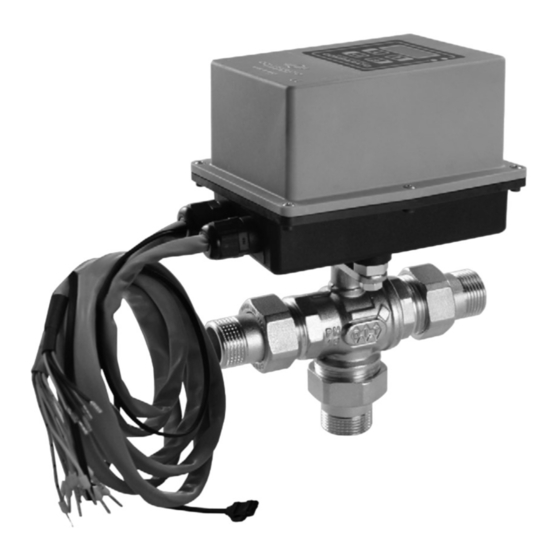
- Page 1 VER. 0.20...
-
Page 2: Table Of Contents
OPERATION DIAMIX PR and COMPAMIX PR motorised electronic mixing valves are used in modern heating and/or cooling systems equipped with floor, wall or ceiling radiating panels for the control of the delivery temperature and the dehumidification system: by exploiting the new functionalities they are able to keep under control the relative humidity inside the house and guarantee the maximum efficiency and the maximum environmental comfort. -
Page 3: Remote Management
REMOTE MANAGEMENT DIAMIX PR and COMPAMIX PR are equipped with a MODBUS RTU interface; using the RS485 serial connection, it is possible to modify all the operating parameters, send commands to the valve, receive in- formation on the operating status and perform diagnostics. -
Page 4: Features Of The Ball Valve
DIAMIX PR / COMPAMIX PR TECHNICAL FEATURES OF BALL VALVES 3-WAY VERTICAL MIXED OUTLET,COMPARATO CONNECTION 3-WAY MIXED VERTICAL OUTPUT ISO 5211 CONNECTION 3/4"• 1" male with unions – thread according to ISO 228/1 1/2"• 3/4" • 1"• 1"1/4 • 1"1/2• 2" Rp female threaded in accordance with 10226-1... -
Page 5: Installation
DIAMIX PR / COMPAMIX PR INSTALLATION VERTICAL MIXED HORIZONTAL-LINE MIXED VERTICAL-LINE MIXED TEMPERATURE SENSOR A - Outlet from primary system (red): during the winter operation (heating) this is the hot fluid inlet; during the summer operation (cooling) this is the cold fluid inlet. . - Page 6 DIAMIX PR / COMPAMIX PR DIAMIX PR COMPARATO CONNECTION DIAMIX PR - COMPAMIX PR ISO 5211 CONNECTION VERTICAL MIXED ONLY IF NECESSARY DIAMIX PR FLOW FROM SYSTEM RETURN PRIMARY SYSTEM RADIANT FLOW FROM SYSTEM RETURN PRIMARY SYSTEM RADIANT COMPAMIX PR...
-
Page 7: Electrical Connections
DIAMIX PR / COMPAMIX PR ELECTRICAL CONNECTIONS 230V / 24V 50Hz CABLE EXTERNAL SENSOR Modbus 5 X 0,5 mm^2 (RFSONDAE) CABLE 17 X 0,5 mm^2 EARTH ROOM THERMOSTAT BROWN TEMPERATURE SENSOR SWITCH BLUE SUMMER/WINTER BLACK GREEN ORANGE RFSONDAT DEHUMIDIFICATION *- 24V DC... -
Page 8: Installation Example
DIAMIX PR / COMPAMIX PR N° Colour Description Type DEHUMIDIFICATION control Digital outlets INTEGRATION command YELLOW SUMMER / WINTER control Max. 24V dc 50mA SUMMER / WINTER switching BLUE Digital inlets Room thermostat WHITE External temperature sensor for climatic function... -
Page 9: Keyboard And Display
DIAMIX PR / COMPAMIX PR HOUSING UNIT HEATING/COOLING SYSTEM RADIANT WITH UMIDITY CONTROL BY MEANS OF A DEHUMIDIFIER SUPPLIED WITH REFRIGERATED WATER FOR RADIANT PANELS Diverter motorised valve Hydraulic compensator System pump Summer / winter control Distribution manifold with electromechanical heads... - Page 10 DIAMIX PR / COMPAMIX PR • PARAMETERS ON THE DISPLAY I = tracking adjustment SUMMER F = fixed-point regulation Can be displayed if parameter “Sensor = 1” F = fixed-point regulation WINTER C = Climate control “E. xx” = cooling mode system flow temperature - summer “A.
- Page 11 DIAMIX PR / COMPAMIX PR • DIGITAL OUTPUT STATUS DISPLAY = output activated (contact closed) OUT1 = Humidity alarm / Dryer control = output not activated (contact open) OUT2 = Condensation alarm / Integrator control OUT3 = Summer / Winter •...
- Page 12 DIAMIX PR / COMPAMIX PR MAIN MENU SUB-MENU FUNCTION Where X means: E = summer. I = winter. E.Imp = selection from external digital inlet E/I * Press “A” or “B” to set the value. Press “C” to save the value and exit the sub-menu.
- Page 13 DIAMIX PR / COMPAMIX PR c = cooling and humidity parameters FLASHING Fixed-point regulation Tracking adjustment Can be displayed if parameter “Sens = 1” To access the menu, when the display shows the "OFF" indication, press the "B" and "C" buttons simultaneously. The display will show the “h c” flashing notice. Press key “B” to enter the cooling and humidity pro- gramming menu.
- Page 14 DIAMIX PR / COMPAMIX PR MAIN MENU SUB-MENU FUNCTION Where XX (%) indicates the maximum relative humidity for the tracking cooling. Press “A” or “B” to set the value. Press “C” to save the value and exit the sub-menu. Adjustment range: 20% to 90% (default 55%).
-
Page 15: Display Alarms
DIAMIX PR / COMPAMIX PR DISPLAY ALARMS ALARM FUNCTION The outlet temperature sensor is disconnected, short-circuited or broken. The motorised valve is forced on the return from the radiant system. When the motorised valve is restored, its normal operation is resumed. - Page 16 DIAMIX PR / COMPAMIX PR • TEMPERATURE AND RELATIVE HUMIDITY SENSOR - code: RFTRUEE10 For the installation and commissioning, refer to the technical manual supplied with the device. It is advisable install the sensor in the room where the condensation is more likely to occur.
-
Page 17: General Warranty Conditions
WARRANTY The DIAMIX PR and COMPAMIX PR motorized valves are covered by a 3-year warranty starting from the date marked on the base of the actuator (year of production). The warranty refers only to the product and does not cover any replacement and/or maintenance and/or any other indirect cost. Products are covered by an Allianz s.p.a. insurance according to current rules regarding the manufacturer's responsibility for any damage arising from defective products. - Page 18 DIAMIX PR / COMPAMIX PR COMPARA TO NELLO SRL...
- Page 19 DIAMIX PR / COMPAMIX PR COMPARA TO NELLO SRL...
Need help?
Do you have a question about the Diamix PR and is the answer not in the manual?
Questions and answers