
Related Manuals for Agito AGM800


Summary of Contents for Agito AGM800
- Page 1 AGM800 Product Manual Rev1.0 draft AGM800 8-axis Central-i Master Controller Product Manual Page 1...
- Page 2 AGM800 Product Manual Rev1.0 draft Revision History Version Description Date Initial Release 11 August 2020 Page 2...
-
Page 3: Table Of Contents
AGM800 Product Manual Rev1.0 draft Table of Content General Description ______________________________________________________ 4 Product Description ________________________________________________________ 4 Product Naming ___________________________________________________________ 4 Contact information _______________________________________________________ 4 Safety, Warranty, Compliance and Environment _______________________________ 5 Safety ___________________________________________________________________ 5 Warranty ________________________________________________________________ 5 Compliance ______________________________________________________________ 5... -
Page 4: General Description
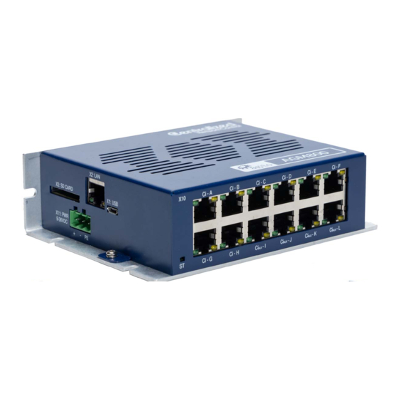
AGM800 Product Manual Rev1.0 draft 1. General Description 1.1 Product Description The following picture illustrates the AG800 series of products, which is an 8-axis Central-i Master controller. Figure 1: AGM800 This product can connect up to 12 Central-i remote devices, of which 8 of them can be remote Figure 2: AGM800 amplifiers. -
Page 5: Safety, Warranty, Compliance And Environment
AGM800 Product Manual Rev1.0 draft 2. Safety, Warranty, Compliance and Environment 2.1 Safety In order to achieve optimum and safe operation of the product, it is important to follow the safety procedures provided in this manual. Only qualified personnel may install, maintain, or repair the product. Before starting installation, maintenance or operation, ensure that all system components are connected to protective earth ground (PE). -
Page 6: Environment Conditions
Agito Akribis Systems Ltd. 2.5.2 Products Rights AGDx, AGCx, AGMx, AGAx, AGIx and AGLx are products designed by Agito Akribis Systems Ltd in Israel. Sales of the products are licensed to Akribis Systems Pte Ltd under intercompany license agreement. -
Page 7: Installation Instruction
AGM800 Product Manual Rev1.0 draft 3. Installation Instruction 3.1 Mechanical Dimensions and Mounting User can mount the AG300C-DRV02 either with the wider side with 4 screws, or the narrower side with 2 screws, according to the 6 open slots shown in the picture below. It is important to securely mount the base plate on the electrical panel to avoid vibration and loosening of the connectors. -
Page 8: Power Rating And Grounding Policy
AGM800 Product Manual Rev1.0 draft 3.2 Power Rating and Grounding Policy 3.2.1 Power Rating The following table presents the absolute maximal power, voltage, current and temperature ratings of the product. Operating (or storing) the product outside of the above defined Absolute Maximal Ratings are not allowed and will damage the product. -
Page 9: General Grounding Policy
PGND (reference voltage for motor/regeneration circuits) ▪ General – will usually be at DC potential close to GND, but not connected internally There are few common interfaces between all Agito’s products, presented in the table below. S/N Name Ground Domain... - Page 10 AGM800 Product Manual Rev1.0 draft In DC devices, unless otherwise stated in the manual, the GND is not connected to PE inside the product. The user must consider the system design and decide about where to connect them. The common recommendation is to connect PE to GND on the DC power supply.
-
Page 11: Electrical Interface
AGM800 Product Manual Rev1.0 draft 3.3 Electrical Interface This section provides a detailed description of all the power and signal interfaces of the product. 3.3.1 Power connectors This section describes all power connectors in the product. 3.3.1.1 Power Figure 4: Power Connector... -
Page 12: Communication Ports
AGM800 Product Manual Rev1.0 draft 3.3.2 Communication Ports The section describes all the communication ports available for the host computer or controller to communication with the product. User can refer to the Communication Protocol Manual for the software details of the communication and a separate Command and Reference Manual for all the supported keywords and parameters. -
Page 13: Can Bus, Rs-232 And Rs-485 (Serial Communication Port)
AGM800 Product Manual Rev1.0 draft 3.3.2.2 CAN Bus, RS-232 and RS-485 (serial communication port) Figure 6: Serial Communication Connectors Connector X8 and X9: CAN, RS232, RS485 Pin # Name Description Digital Ground RS232_RX RS232 input (receive at product) RS232_TX RS232 output (transmit from product) -
Page 14: Micro Usb
AGM800 Product Manual Rev1.0 draft 3.3.2.3 Micro USB Figure 7: USB Connector Connector X1: USB Pin # Name Description Data- Data+ USB OTG ID Connector Description: Micro-USB 2.0 B-Type Mating Connector Part number: Any Micro-USB 2.0 B-Type cable Note – USB to RS232 Bridge. -
Page 15: Central-I Ports
Typically, the Central-i link can be connected by any standard CAT5e shielded cable, up to 10m. However, a hardware option is available for up to 100m long connection between AGM800 and remote devices. Please consult your sales representative for such option. -
Page 16: Operation Instruction
AGM800 Product Manual Rev1.0 draft 4. Operation Instruction 4.1 Software Configuration This manual uses the product with a Linear DC Brushless motor as an example for illustration of the configuration and operation. For advanced configuration and operation, refer to the respective software manuals. - Page 17 AGM800 Product Manual Rev1.0 draft Click ‘Next’ to setup position, velocity and motor stuck protection. Fill in the limits according to the application requirements. Figure 13 Position and Velocity Protection Click ‘Next” to configure current and voltage limits. It is important to refer to motor’s specifications.
-
Page 18: Tuning
AGM800 Product Manual Rev1.0 draft 4.2 Tuning 4.2.1 Auto Velocity and Position Loop Tuning 1. System Identification. Select TUNE -> IDEN. Click on “Begin Identification” button to perform system identification. Figure 16 Begin System Identification When the identification is completed successfully, the plant’s transfer function, like the picture on the... - Page 19 AGM800 Product Manual Rev1.0 draft 4. Once Auto-Tuning is completed, click ‘Write to Controller’ to download the calculated gains into the controller. Figure 19 Download the parameters to the controller 5. Check the motion performance in the Motions Tab, setting the required motion profile and click “Go 1”...
-
Page 20: Manual Velocity And Position Loop Tuning
AGM800 Product Manual Rev1.0 draft 4.2.2 Manual Velocity and Position Loop Tuning Select TUNE -> PIV. in the tune option, adjust the proportional (“PI, gain”) and integral (“PI, integral”) gains of velocity loop, click “Apply Vel Command” to check the performance. -
Page 21: Maintenance And Servicing Instruction
AGM800 Product Manual Rev1.0 draft 5. Maintenance and Servicing Instruction Possible fault conditions: Condition Potential Cause Possible Resolution Power is On but no LED light Power connector is loose Check power connector, measure power supply voltage using a volt-meter. Firmware is corrupted Download firmware using PCSuite. - Page 22 AGM800 Product Manual Rev1.0 draft Mechanical resonance. Add a software low pass filter from PCSuite’s TUNE -> PIV, Velocity Filters tab. Do advanced auto tuning to allow PCSuite identify and apply a suitable filter. Perform TUNE->IDEN and TUNE -> DESI (Expert ->...
- Page 23 AGM800 Product Manual Rev1.0 draft The axis is configured in a Check all motion related wrong operating mode or configurations. function, e.g. as a slave axis or another master. Motor or drive’s connector is Check motor power and loose. drive’s connection The motor is faulty.
Need help?
Do you have a question about the AGM800 and is the answer not in the manual?
Questions and answers
How to Communicate with Labview?
The Agito AGM800 can be communicated with using LabVIEW through its .NET API. The API is compatible with Windows .NET Standard, allowing integration with LabVIEW and other environments. To establish communication, install the .NET API available in the NuGet package manager and use the necessary .NET functions within LabVIEW to send and receive commands. The controller supports TCP/IP communication using ASCII string commands or binary CAN format.
This answer is automatically generated
@Mr. Anderson , I **** not Able to Get Connection Status, I Uploaded the Image for your Reference. Previously we used AGD155 AAmotion.dll for the Communication, but Now the Replaced with AGM800 Controllers, is that dll is same or Different?