Table of Contents
Advertisement
Quick Links
Advertisement
Table of Contents

Related Manuals for Canoga Perkins EDGEACEESS 9145E

Summary of Contents for Canoga Perkins EDGEACEESS 9145E
- Page 1 9145E Network Interface Device User Manual...
- Page 2 Canoga Perkins and any unauthorized use or disclosure of such drawings, specifications and information is prohibited. Canoga Perkins reserves the right to change or update the contents of this manual and to change the specifications of its products at any time without prior notification. Every effort has been made to keep the information in this document current and accurate as of the date of publication or revision.
- Page 3 9145E Ethernet Network Interface Device User Manual CAUTION! This product may contain a laser diode emitter operating at a wavelength of 1300 nm - 1600 nm. Use of optical instruments (for example: collimating optics) with this product may increase eye hazard.
- Page 4 The 9145E DC has a nominal operating DC voltage of -48 VDC and passes the minimal steady state DC operating voltage of -40 VDC in accordance with GR-1089 Issue 4, which references American National Standards Institute (ANSI) T1.315, Table 1. Additionally, Canoga Perkins design allows for a minimal steady state of -36VDC.
- Page 5 9145E Ethernet Network Interface Device User Manual Surge Protection The AC powered 9145E does not contain an internal Surge Protective Device. An external Surge Protective Device (SPD) should be used at the AC input of the network equipment according to facilities procedures and as defined by the National Electric Code (NEC).
- Page 6 The authority to operate this equipment is conditioned by the requirements that no modifications will be made to the equipment unless the changes or modifications are expressly approved by the Canoga Perkins Corporation. To Users of Digital Apparatus in Canada: This Class A digital apparatus meets all requirements of the Canadian interference-causing equipment regulations.
- Page 7 9145E Ethernet Network Interface Device User Manual Double Pole/Neutral Fusing On the 9145E a fuse may be in place in the neutral path on the AC power supply. After operation of the fuse, parts of the equipment that remain energized might represent a hazard during servicing.
-
Page 9: Table Of Contents
9145E Ethernet Network Interface Device User Manual Contents Chapter 1. Introduction ................ 13 Description ......................13 9145E Specifications....................14 Physical Characteristics ....................14 Environmental Characteristics ..................14 Power Requirements....................... 14 Regulatory Compliance....................14 Hardened 9145E Specifications ................15 Physical Characteristics ....................15 Environmental Characteristics .................. - Page 10 Service Data Ports ....................20 Management Ports ....................20 EIA-232 Console Port ..................... 20 Ethernet Management Port ..................... 21 Port Default Settings ....................21 Power Connectors....................21 Power Requirements....................... 21 Single AC Power Base Unit .................... 22 Redundant AC Power Base Unit..................22 Single DC Power Base Unit ....................
- Page 11 9145E Ethernet Network Interface Device User Manual Chapter 4. Operation ................39 Power-Up and Front Panel Functions ..............39 Ethernet Management LEDS ..................39 SFP/UTP Port Status LEDS.................... 41 Interface Management ................... 41 Setting Up the VT-100 Terminal..................41 Chapter 5. Troubleshooting ..............43 Optical Power Loss ....................
-
Page 13: Chapter 1. Introduction
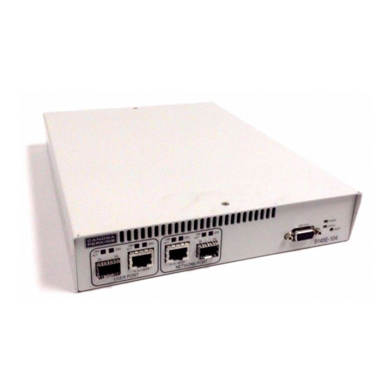
Chapter 1 Introduction 1.1 Description The 9145E (see Figure 1-1) is Canoga Perkins second generation Network Interface Device (NID) that can be used by a Service Provider (SP) to provide layer 1 and layer 2 termination of Ethernet services. The 9145E encompasses features and functions needed by SPs to deliver Metro Ethernet Forum (MEF) compliant Ethernet services with end-to-end Quality of Service (QoS) guarantees and Operation, Administration, Maintenance and Provisioning (OAM&P) capabilities. -
Page 14: 9145E Specifications
Introduction 9145E Ethernet Network Interface Device User Manual 9145E Specifications 1.2 9145E Specifications 1.2.1 Physical Characteristics • Dimensions: 1.75" H x 8.25" W x 11.5" D (44.5 x 209.5 x 292 mm) • Weight: 4.75 lb to 5.1 lb (2.15 Kg to 2.31 Kg) (depending on model) 1.2.2 Environmental Characteristics •... -
Page 15: Hardened 9145E Specifications
Introduction 9145E Ethernet Network Interface Device User Manual Hardened 9145E Specifications 1.3 Hardened 9145E Specifications 1.3.1 Physical Characteristics • Dimensions: 1.75" H x 8.25" W x 11.5" D (44.5 x 209.5 x 292 mm) • Weight: 4.75 lb to 5.1 lb (2.15 Kg to 2.31 Kg) (depending on model) 1.3.2 Environmental Characteristics •... -
Page 16: Rack Mounting
The customer is required to order the brackets required (see Figure 1-2) for their particular rack installation. Figure 1-1 9145E Mounting Brackets 1.4.2 Wall Mounting Canoga Perkins includes a mounting template in the shipping container (see Figure 1-3) to assist the customer in mounting the 9145E on a wall. 1" 3"... -
Page 17: Chapter 2. Functional Description
Functional Description 9145E Ethernet Network Interface Device User Manual Base Unit Chapter 2 Functional Description 2.1 Base Unit The 9145E is designed with front-panel data and management ports and rear-panel power and ground connectors. This design allows for a multitude of power and port options. The 9145E is available as a normal (see Table 2-1) or hardened (see Table 2-2) unit. -
Page 18: Hardware Configuration
Functional Description 9145E Ethernet Network Interface Device User Manual Hardware Configuration Table 2-1. 9145E Model Numbers and Configuration MODEL DESCRIPTION NUMBER 9145E-204-9-0 9145e 2 Port Std Model Redundant AC/DC Power Table 2-2. Hardened 9145E Model Numbers and Configuration MODEL DESCRIPTION NUMBER 9145E-301-1-0 9145e 4 Port Adv Model Single -48v DC Power... -
Page 19: Rear Panel
Functional Description 9145E Ethernet Network Interface Device User Manual Hardware Configuration 6. One Network Port (for service data) with both SFP and UTP connectors 7. One Multi-Purpose Port (service data and/or management traffic) with both SFP and UTP connectors Ethernet LC (SFP) RJ45 (UTP) Management... -
Page 20: Service Data Ports
Functional Description 9145E Ethernet Network Interface Device User Manual Service Data Ports 2.3 Service Data Ports The Service Data Ports (see Figure 2-1) provide both fixed UTP and SFP connectors. The user can configure the 9145E through software to allow for either the RJ45 or SFPmodule connector within each port to be active. -
Page 21: Ethernet Management Port
Functional Description 9145E Ethernet Network Interface Device User Manual Port Default Settings 2.4.2 Ethernet Management Port The Ethernet Management port is used for remote management of the 9145E. The 9145E has a management interface with an RJ45 UTP connector. The management port can sense and automatically cross-over the Tx and Rx pairs. -
Page 22: Single Ac Power Base Unit
Functional Description 9145E Ethernet Network Interface Device User Manual Power Connectors 2.6.2 Single AC Power Base Unit The Single AC powered 9145E base unit (see Figure 2-4) has an IEC 320 power connector on the rear panel. An appropriate AC power cord is supplied with the unit. Figure 2-4 Single AC Power 2.6.3 Redundant AC Power Base Unit The Redundant AC powered 9145E base unit (see Figure 2-5) has two power connectors on the... -
Page 23: Redundant Dc Power Base Unit
Functional Description 9145E Ethernet Network Interface Device User Manual LED Indicators 2.6.5 Redundant DC Power Base Unit The Redundant DC powered 9145E base unit (see Figure 2-7) has two 3-terminal receptacles on the rear panel. Two DC terminal blocks are supplied with the unit. Figure 2-7 Redundant DC Power 2.6.6 AC/DC Power Base Unit The AC/DC powered 9145E base unit (see Figure 2-8) has two power interfaces on the rear-... -
Page 24: Management Section Leds
Functional Description 9145E Ethernet Network Interface Device User Manual LED Indicators 2.7.1 Management Section LEDs Table 2-4 provides the indications supplied by the STATUS, POWER, SPD, and LNK/ACT LEDs, located to the right of the Ethernet Management and Console ports. Table 2-4. -
Page 25: Data Interface Section Leds
Functional Description 9145E Ethernet Network Interface Device User Manual LED Indicators 2.7.2 Data Interface Section LEDs Table 2-5 represents the indications supplied by the SPD and LNK/ACT LEDs of the User, Network, and Multipurpose ports. Indications apply to both the SFP and UTP LEDs. Table 2-5. - Page 26 Functional Description 9145E Ethernet Network Interface Device User Manual LED Indicators...
-
Page 27: Chapter 3. Installation
Keep the shipping container and all packing materials until the unit is installed and fully operational. In the event that the unit needs to be returned, contact Canoga Perkins Customer Service for a Return Authorization Number (RMA) and instructions for return shipment. -
Page 28: Mounting Options
Installation 9145E Ethernet Network Interface Device User Manual Mounting Options Figure 3-1 Unpacking the 9145E 3.3 Mounting Options The 9145E can be rack mounted, wall mounted, or placed on any horizontal flat surface such as a shelf or table. 3.3.1 Rack Mounting One 9145E can be mounted in either a 19"... - Page 29 Installation 9145E Ethernet Network Interface Device User Manual Mounting Options Table 3-1. Rack Mount Kits Rack Mount Kit Part Number Component Part Number Bracket, rack mount,single, 19” 6213614-119 Rack Mount Bracket 1802-2016 Kit, 19" Single Unit Screw, flat head,8-32 x 0.25” 80680041 Bracket, rack mount,single, 23”...
- Page 30 Installation 9145E Ethernet Network Interface Device User Manual Mounting Options Mounting One 9145E in a 19" or 23" Rack - To rack mount one 9145E, perform the following steps: 1. Install the Rack Mount Bracket Kit, 19" Single Unit or Rack Mount Bracket Kit, 23" Single Unit. The Rack Mount Kit includes two mounting brackets, and the screws required to attach the brackets to the 9145E.
-
Page 31: Wall Mounting
Installation 9145E Ethernet Network Interface Device User Manual Mounting Options 1. Install the Rack Mount Bracket Kit, 19" Dual Unit or Rack Mount Bracket Kit, 23" Dual Unit. The Rack Mount Kit includes two rack mount brackets, two center brackets, a strap, a rear bracket, and the screws required to attach the brackets to the 9145Es. - Page 32 Two number 8 screws and wall anchors, which are not provided by Canoga Perkins, are used for wall mounting. The keyholes are designed so that the 9145E can be mounted in three positions: with front panel facing the floor, to the right or to the left (see Figure 3-8).
-
Page 33: Horizontal Flat Surface Mounting
The 9145E requires at least one inch of unobstructed space around the perimeter for ventilation. Canoga Perkins recommends a space of 3 to 5 inches be left unobstructed to allow for SFP module access, cable access and power connections. To install the 9145E on a flat surface, place the 9145E on a secure flat surface such as a table, a shelf, or a desk within reach of the power and fiber optic cables. -
Page 34: Installing The Sfp Modules
1. Determine which SFP modules are required for the User, Network, and Multipurpose ports. Please contact Canoga Perkins Technical Support for an updated list of supported SFPs. 2. Insert a module into each available port and push firmly to seat the module (see Figure 3-10). -
Page 35: Dc Power
Installation 9145E Ethernet Network Interface Device User Manual Connecting the Electrical Power 3.5.2 DC Power CAUTION:The 24 VDC and 48VDC 9145Es are only intended to be used in a restricted access location in accordance with Articles 110-16, -17, and -18 of the National Electric Code ANSI/NFPA 70. NOTE: The DC Power Terminal Block is removable for ease of installation and replacement. - Page 36 Installation 9145E Ethernet Network Interface Device User Manual Connecting the Electrical Power 11. Insert the terminal block into the socket. The 9145E will power up. TERMINAL SCREWS Figure 3-11 Connect D.C. Power NOTE:Accidently reversing polarity will NOT damage the power supply or source.
-
Page 37: Grounding
Installation 9145E Ethernet Network Interface Device User Manual Connecting the Electrical Power 3.5.3 Grounding A grounding lug kit is included in the 9145E accessory tray. Connect a 6AWG grounding cable to the 9145E as follows (see Figure 3-12): 1. Strip approximately ¾-inch of insulation from the end of the grounding cable. 2. -
Page 38: Connecting The Fiber Optic And Utp Ethernet Cables
Installation 9145E Ethernet Network Interface Device User Manual Connecting the Electrical Power 3.5.4 Connecting the Fiber Optic and UTP Ethernet Cables 3.5.4.1 Optical Fiber Cable Installation NOTE: To avoid damaging the fiber end-surface or connector, use extreme care when installing or removing cables. Connect the Optical Fiber cables to the SFP modules as follows: 1. -
Page 39: Chapter 4. Operation
Operation 9145E Ethernet Network Interface Device User Manual Power-Up and Front Panel Functions Chapter 4 Operation 4.1 Power-Up and Front Panel Functions The LEDs on the front panel indicate the system and port status of the 9145E (see Figure 4-1). During power-up, all LEDs on the 9145E will turn amber. - Page 40 9145E Ethernet Network Interface Device User Manual Operation Power-Up and Front Panel Functions Table 4-1. Power, Status, and Ethernet Management LED Indications LED Name State Condition No Power Green Normal operation Amber System self-test in progress Blinking Amber System is booting / Loopback mode STATUS Major alarms including Link Loss at the User, Extension or MP Port (if MP port is supported)
-
Page 41: Sfp/Utp Port Status Leds
Operation 9145E Ethernet Network Interface Device User Manual Interface Management 4.1.2 SFP/UTP Port Status LEDS The Link/Activity (LNK/ACT) LEDs are located above the SFP and UTP Ports of the each port section (see Figure 4-1). See Table 4-2 to determine the current condition of the User Ports. Table 4-2. - Page 42 9145E Ethernet Network Interface Device User Manual Operation Interface Management NOTE: The Microsoft Vista operating system does not include HyperTermi- nal. If your terminal interface computer uses Windows Vista, you will need to use a separate terminal emulation program. The following steps describe how to set up HyperTerminal on your PC. 1.
-
Page 43: Chapter 5. Troubleshooting
Troubleshooting 9145E Ethernet Network Interface Device User Manual Optical Power Loss Chapter 5 Troubleshooting This chapter covers identifying fault conditions and determining corrective action. The front panel LEDs provide both normal and fault information. To aid troubleshooting, Tables 5-1and 5-2 list all LED functions and indications. - Page 44 9145E Ethernet Network Interface Device User Manual Troubleshooting Fault Conditions Table 5-1. Power, Status, and Ethernet Management LED Indications LED Name State Condition No Power Green Normal operation Amber System self-test in progress / Loopback mode Blinking Amber System is booting STATUS Major alarms including Link Loss at the User, Extension or MP Port (if MP port is supported)
-
Page 45: Link Loss Forwarding
Troubleshooting 9145E Ethernet Network Interface Device User Manual Fault Conditions Table 5-2. User, Network, and Multipurpose Port LED Indications LED Name State Condition 10BaseT Auto Connector Not Selected Green 1000BaseT 100BaseTX Amber System Test Remote Fault (SFP Only) Blinking Red Invalid/Unsupported SFP installed (SFP Only) Slow Blinking Green* Connector Selected with No Link No link... -
Page 46: Running Diagnostics
Latency/Jitter Testing measures and reports performance and quality of the link between the 9145E and another Canoga Perkins device. Results reported include the Frame Loss Ratio (FLR), and the minimums, average, and maximums for latency and jitter. For latency and jitter testing instructions, see the 9145E Ethernet NID Software User Manual. -
Page 47: User Mode
Troubleshooting 9145E Ethernet Network Interface Device User Manual Loopback Diagnostics NID Software User Manual). When in loopback mode, the 9145E filters and discards all service frames. The 9145E can be configured to swap the origination and destination MAC Addresses and to recalculate the looped frame's CRC. -
Page 48: Network Mode
9145E Ethernet Network Interface Device User Manual Troubleshooting Loopback Diagnostics 5.4.2 Network Mode Network Mode loops data received on the Network Port Rx through the Local User side to the Network Port Tx. Data is not sent out the local User Port Tx and incoming data on the local User Port Rx is ignored (see Figure 5-4). -
Page 49: Chapter 6. Maintenance
Measurement tolerance is +/- 0.5 dBm. 5. If the reading is low, repeat the measurement with a different test cable. If the power level is still not within range, call Canoga Perkins Technical Support. -
Page 50: Measuring Receiver Input Power
7. Compare the receiver input power with the sensitivity level listed on the optical specifications sheet, located in the Client Support Area of the Canoga Perkins web site. The power level must be within the sensitivity range listed on the data sheet. If not, contact Canoga Perkins Technical Support. -
Page 51: Calculating Fiber Link Attenuation
1 dB for the connector loss from the patch cables between the 9145E and the local device. (Each fiber connection can generate 0.5 dB of additional loss.) NOTE: If you cannot determine the Rx sensitivity, contact Canoga Perkins Technical Support for assistance. - Page 54 CANOGA PERKINS CORPORATION 20600 Prairie Street Chatsworth, California 91311-6008 USA Phone: (818) 718-6300 FAX: (818) 718-6312 Web Site: www.canoga.com Email: fiber@canoga.com...
Need help?
Do you have a question about the EDGEACEESS 9145E and is the answer not in the manual?
Questions and answers