Table of Contents
Advertisement
Advertisement
Chapters
Table of Contents

Subscribe to Our Youtube Channel
Related Manuals for Siemens Water Technologies Series


Summary of Contents for Siemens Water Technologies Series
- Page 1 ACUTEC™ 35 GAS DETECTION SYSTEM BOOK NO. WT.050.130.000.UA.IM.1108...
- Page 2 Statements and instructions set forth herein are based upon the best information and practices known to Siemens Water Technologies Corp., but it should not be assumed that every acceptable safety procedure is contained herein. Of necessity this company cannot guarantee that actions in accordance with such statements and instructions will result in the complete elimination of hazards and it assumes no liability for accidents that may occur.
-
Page 3: Table Of Contents
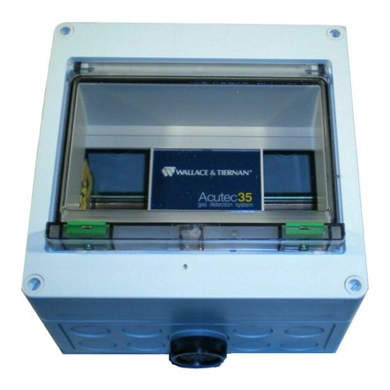
ACUTEC™ 35 SYSTEM INTRODUCTION The Siemens Water Technologies Series 50-130 Acutec™ 35 Gas Detec- tion system is an on-line monitoring system for the detection of chlorine ), sulfur dioxide (SO ), or ammonia (NH ) gas in ambient air. Alarm contacts are provided to transfer at user selectable setpoints. -
Page 4: Very Important Safety Precautions
HANDLE BATTERIES WITH CARE, BEING CERTAIN NOT TO SHORT TERMINALS, AS SEVERE ARCING OR EXPLOSION COULD OCCUR. TO ENSURE PROPER AND SAFE OPERATION OF THIS EQUIPMENT, USE ONLY SIEMENS WATER TECH- NOLOGIES LISTED PARTS EXCEPT COMMERCIALLY AVAILABLE PARTS AS IDENTIFIED BY COMPLETE DESCRIPTION ON PARTS LIST. - Page 5 Fax: (856) 507-4125 NOTE Minor part number changes may be incorporated into Siemens Water Technologies products from time to time that are not immediately reflected in the instruction book. If such a change apparently has been made in your equipment and does not appear to be reflected in your instruction book, contact your local Siemens Water Technologies sales office for information.
-
Page 6: Regional Offices
1901 West Garden Road Vineland, NJ 08360 TEL: (856) 507-9000 FAX: (856) 507-4125 CANADA If the equipment was purchased directly from Siemens Water Technologies Canada, Inc., contact the nearest office indicated below. ONTARIO QUEBEC 250 Royal Crest Court 243 Blvd. Brien... - Page 7 ACUTEC™ 35 SYSTEM SECTION 1 – TECHNICAL DATA List Of Contents PARA./DWG. NO. Technical Data ............1.1 Interferences ............1.2 WT.050.130.000.UA.IM.1108...
-
Page 8: Technical Data
ACUTEC™ 35 SYSTEM Technical Data Gas Ranges Standard Minimum Maximum Range Range Range Chlorine 0 - 10 ppm 0 - 5 ppm 0 - 50 ppm Sulfur Dioxide 0 - 20 ppm 0 - 10 ppm 0 - 100 ppm Ammonia 0 - 100 ppm 0 - 50 ppm... - Page 9 ACUTEC™ 35 SYSTEM Interferences Electrochemical sensors are, by nature, not 100% selective; therefore, they can exhibit response to other gases present in ambient air. The following tables list the possible interferences that may occur when using the different gas sensors. The tables indicate the relative response of the sensor to 1 ppm of the listed gas, expressed in terms of relative ppm signal.
- Page 10 ACUTEC™ 35 SYSTEM AMMONIA Interference Gas Response Methyl Mercaptan Hydrogen Sulfide Hydrogen Nitrogen Dioxide -0.2 Chlorine -0.2 WT.050.130.000.UA.IM.1108...
- Page 11 ACUTEC™ 35 SYSTEM SECTION 2 – INSTALLATION List Of Contents PARA./DWG. NO. Overview ..............2.1 General Installation ..........2.2 Mounting Power Supply and Receiver Modules ..2.3 Electrical Connections ..........2.4 Installation of Power Supply Module ....... 2.5 Illustrations Dimensions Single Point Detection System ......
- Page 12 ACUTEC™ 35 SYSTEM Overview The Series 50-130 Gas Detection System consists of modular com- ponents that can be used in a variety of configurations to fit specific application requirements. Following is a brief description of the major system components. More detailed information follows later in this manual.
-
Page 13: Installation
ACUTEC™ 35 SYSTEM General Installation NOTE: Power supply or Receiver modules may be shipped with pro- tective transparent plastic covers. These covers should be peeled off and discarded. System enclosures, Battery Back-up units, and Sensor/Transmitters are all designed for surface mounting using screws or bolts inserted through the recessed mounting holes at each corner of the enclosures. -
Page 14: Mounting Power Supply And Receiver Modules
ACUTEC™ 35 SYSTEM Mounting Power Supply and Receiver Modules (See Dwg. 50.130.000.001) Power Supply and Receiver Modules are mounted to a standard 35 x 7.5 mm DIN rail in the detection system enclosure. The spring loaded clip with the loop holds the module to the rail. To install modules, first slide the bottom of the module under the rail. -
Page 15: Installation Of Power Supply Module
ACUTEC™ 35 SYSTEM Installation of Power Supply Module The Power Supply Module used in the gas detection system operates on ac supplies of 85 volts to 255 volts, at 50/60 Hz. No adjustments or modifications are required of the user. WT.050.130.000.UA.IM.1108... -
Page 16: Single Point Detection System
ACUTEC™ 35 SYSTEM 4-5/16” 7-3/16” (110) (183) 6-9/16” (167) 7-1/16” (179) 6-1/2” (165) NOTE: ( ) INDICATES DIMENSIONS IN MILLIMETERS. SINGLE POINT DETECTION SYSTEM - DIMENSIONS 50.130.100.001 ISSUE 3 8-08 WT.050.130.000.UA.IM.1108... -
Page 17: Dual Point Detection System
ACUTEC™ 35 SYSTEM 4-3/8” 10” (111) (254) 9-7/16” (240) 7-1/16” (179) 6-1/2” (165) NOTE: ( ) INDICATES DIMENSIONS IN MILLIMETERS. DUAL POINT DETECTION SYSTEM - DIMENSIONS 50.130.100.002 ISSUE 3 8-08 WT.050.130.000.UA.IM.1108... - Page 18 ACUTEC™ 35 SYSTEM 1-1/8” (29) 1-1/16” 3-3/4” (27) (95) 3-1/8” (79) 3-1/8” (79) 3-3/4” 2-5/8” (95) (67) 2-1/4” (57) 1-3/8” (35) 3/4” (19) NOTE: ( ) INDICATES DIMENSIONS IN MILLIMETERS. A ACCESSORY ITEM FURNISHED ONLY IF SPECIFICALLY LISTED IN QUOTATION. WHEN THE GAS GENERATOR IS USED, THE UNIT MUST BE MOUNTED AS SHOWN.
-
Page 19: Battery Back-Up
ACUTEC™ 35 SYSTEM 3-1/2” 4-3/8” (89) (111) 3-3/4” (95) 7-1/8” (181) 6-1/2” (165) NOTE: ( ) INDICATES DIMENSIONS IN MILLIMETERS. BATTERY BACK-UP - DIMENSIONS 50.130.100.004 ISSUE 2 7-98 WT.050.130.000.UA.IM.1108... -
Page 20: Single Point Detection System
ACUTEC™ 35 SYSTEM NOTE: WIRING BY SIEMENS WATER TECHNOLOGIES. FIELD WIRING MUST CONFIRM TO LOCAL ELECTRICAL CODES. SINGLE POINT DETECTION SYSTEM - INSTALLATION WIRING 50.130.130.001 ISSUE 2 11-08 WT.050.130.000.UA.IM.1108... -
Page 21: Dual Point Detection System
ACUTEC™ 35 SYSTEM NOTE: WIRING BY SIEMENS WATER TECHNOLOGIES. FIELD WIRING MUST CONFIRM TO LOCAL ELECTRICAL CODES. DUAL POINT DETECTION SYSTEM - INSTALLATION WIRING 50.130.130.002 ISSUE 2 11-08 WT.050.130.000.UA.IM.1108... - Page 22 ACUTEC™ 35 SYSTEM WT.050.130.000.UA.IM.1108...
-
Page 23: Operation
ACUTEC™ 35 SYSTEM SECTION 3 – OPERATION List Of Contents PARA./DWG. NO. Power Supply Operation ......... 3.1 Receiver Module Operation ........3.2 Configuration Switches ........3.2.1 Range Selection ........... 3.2.2 Setpoint Selection ..........3.2.3 Relay Configuration ..........3.2.4 Alarm Delay ............3.2.5 Display Intensity .......... -
Page 24: Power Supply Operation
ACUTEC™ 35 SYSTEM Power Supply Operation (See Dwg. 50.130.000.001) The power supply provides a regulated 13.7 Vdc to Receiver Modules and to the Battery Back-up through three sets of terminals at the top of the module. Total output current is rated at one amp. The power supply provides a SPDT relay contact which de-energizes when ac power is lost. - Page 25 ACUTEC™ 35 SYSTEM b. Unplug the terminal connectors on the top and bottom of the receiver module. Refer to Figure 3.1. c. Remove the receiver module from the enclosure by pulling out the plastic clip at the top of the module while removing the module from the rail in the back of the enclosure.
- Page 26 ACUTEC™ 35 SYSTEM f. Position the electronic assembly as shown in Figure 3.2. Identify DIP SWITCH BANKS A through D. Figure 3.2 - Top View of Module Electronics Without Housing g. Adjust the Receiver DIP switch functions as needed, by referring to the Figure 3.3.
- Page 27 ACUTEC™ 35 SYSTEM BANK A ACTIVATE WARNING SETPOINT - % OF RANGE ALARMS BELOW SETPOINT ABOVE SETPOINT BANK B ALARM ALARM SETPOINT - % OF RANGE DELAY SECONDS SECONDS BANK C DISPLAY RANGE RELAY 3 NORMAL HORN ALARM LATCHING ENERG. ALARM NON- NORMAL...
-
Page 28: Range Selection
ACUTEC™ 35 SYSTEM 3.2.2 Range Selection Receivers are factory configured for the Standard Operating Range and Setpoints as listed below. Factory Settings of Range and Setpoints Standard Warning Alarm Range Setpoint Setpoint Chlorine 0 - 10 ppm 1 ppm 3 ppm Sulfur Dioxide 0 - 20 ppm 2 ppm... - Page 29 ACUTEC™ 35 SYSTEM For instance, if you have a receiver range of 0 to 10 ppm and want to adjust a setpoint for 3 ppm, set the appropriate DIP switches to the binary number for 30% from the SETPOINT SELECTION table, below. Setpoint Selection Switch Pos.
-
Page 30: Relay Configuration
ACUTEC™ 35 SYSTEM The Gas Detector is factory set to alarm when gas concentrations above the chosen setpoints are exceeded; however, if switch A1 is set to the ON position, alarms will be initiated when gas concentration is below the setpoint. 3.2.4 Relay Configuration •... -
Page 31: Alarm Delay
ACUTEC™ 35 SYSTEM the push-button switch is pressed or when the remote reset terminals are connected, silencing the external horn. 3.2.5 Alarm Delay A time delay precedes the activation of alarm relays to eliminate false alarms due to electrical transients. The delay is factory set to two seconds, but can be changed to 10 seconds with switch B1. -
Page 32: Alarm Acknowledge And Reset
ACUTEC™ 35 SYSTEM NOTE: It is strongly recommended that sensors be powered overnight upon initial startup before adjustments are made and before con- nections are made to alarm relays. Sensors which are powered for the first time may remain in an alarm state beyond the five minute inhibit period and may take several hours to fully stabilize. -
Page 33: Lamp And Horn Test
ACUTEC™ 35 SYSTEM hours, the microcomputer in the receiver activates the Gas Generator and monitors the output of the gas sensor. During the time when an Auto-Test is in progress, the alarm relays are inhibited. This is indicated by the warning and alarm indicators alternately flashing. -
Page 34: Manual Auto-Test
ACUTEC™ 35 SYSTEM before inhibit was initiated, but the relays will not activate. Transmitters may be calibrated while the inhibit is on without setting off external alarms. When the receiver is in inhibit, the display reads the actual signal down to 0 ppm, and will read negative if the sensor is out of calibration. -
Page 35: Installation Wiring
ACUTEC™ 35 SYSTEM has cleared. The remote reset input will not activate any of the testing or inhibit functions of the receiver. 3.3.8 Analog Output Monitor Receivers provide an isolated 4-20 mA output signal for interface with recorders, data loggers, or computer systems. The span of the 4-20 mA signal is the same as the range of the receiver selected during the receiver configuration. -
Page 36: Sensor Location (Chlorine, Sulfur Dioxide, And Ammonia)
ACUTEC™ 35 SYSTEM 3.4.2 Sensor Location (Chlorine, Sulfur Dioxide, And Ammonia) Chlorine and Sulfur Dioxide gases are heavier than air and will tend to ac- cumulate near the floor in a closed room with little air movement. Ideally, these sensors should be located one to two feet off the floor in closed storage rooms, but may be located at higher elevations where good air flow will quickly mix any leaking gas throughout the space. - Page 37 ACUTEC™ 35 SYSTEM GAS DETECTOR SYSTEM - ASSEMBLY 50.130.160.001 ISSUE 1 8-08 WT.050.130.000.UA.IM.1108...
- Page 38 ACUTEC™ 35 SYSTEM WT.050.130.000.UA.IM.1108...
-
Page 39: Illustrations
ACUTEC™ 35 SYSTEM SECTION 4 – SERVICE List Of Contents PARA./DWG. NO. Removing Unit from Service ........4.1 Sensor Service ............4.2 General Sensor Response Test ......4.2.1 Chlorine Sensor Response Test ......4.2.2 Sulfur Dioxide Sensor Response Test ..... 4.2.3 Ammonia Sensor Response Test ...... -
Page 40: Removing Unit From Service
ACUTEC™ 35 SYSTEM Removing Unit From Service The low-voltage drop-out relay on the Battery Back-up unit is energized as soon as power is applied to the power supply module. Once energized, the coil current is supplied from the power supply module initially, but will be supplied from the battery if power is removed from the power supply module, or if the module is disconnected from the battery. -
Page 41: Sulfur Dioxide Sensor Response Test
ACUTEC™ 35 SYSTEM verified, immediately remove the bottle as prolonged exposure to high concentrations of chlorine will shorten the life of the sensor. If no re- sponse is observed, the sensor may need to be replaced. See paragraph 4.8, Troubleshooting. 4.2.3 Sulfur Dioxide Sensor Response Test Sulfur Dioxide sensors can be tested with fresh powdered sodium bisulfite... -
Page 42: Gas Generator Replacement
If the sensor still does not respond, test the sensor with the appropriate Sensor Response Test described in paragraph 4.2. If the sensor does not respond, replace it. If the sensor responds properly, contact Siemens Water Technologies for assistance with the Generator. -
Page 43: Zero Adjustment
ACUTEC™ 35 SYSTEM Prior to calibration, remove the cover from the Sensor/Transmitter enclo- sure and connect a DVM to the test points as shown in Figure 4.1. The test points will provide a 0-1.00 Vdc signal proportional to transmitter range. For example, a range of 0 to 10 ppm, 0 ppm is 0.00 volts and 10.0 ppm is 1.00 volts. -
Page 44: Range Adjustment
ACUTEC™ 35 SYSTEM Connect the DVM to the transmitter test points. Adjust the span po- tentiometer until a stable voltage reading is obtained according to the following equation: V = Span Gas Concentration ÷ Transmitter Range As an example, if the calibration gas is 3 ppm and the Sensor/Transmitter range is 0 to 5 ppm, the voltage should be adjusted to 3 ÷... -
Page 45: Routine Service
Verify that the Battery Back-up works by removing ac power. • QUARTERLY Adjust the sensor span potentiometer (optional—requires a gas cali- bration device). (Not supplied by Siemens Water Technologies.) NOTE: Span adjustment is recommended only when a precise indica- tion of gas level is required. WT.050.130.000.UA.IM.1108... -
Page 46: Troubleshooting
ACUTEC™ 35 SYSTEM Troubleshooting Trouble Remedy Receiver LEDs and indicators do Check the fuse. If the fuse is blown, replace the fuse. If not light when power is applied not, go to step 2. to the system. Check wiring from the Power Supply Module to the Receiver Module (see Dwgs. - Page 47 PERSONAL INJURY OR DEATH MAY RESULT FROM EXPOSURE TO THE DESIGNATED GAS. TEST ASSEMBLY WITH DESIG- NATED GAS UPON START-UP, MONTHLY, AND IF EXPOSED TO CHEMICALS. REPLACE OR REPAIR ASSEMBLY IMMEDIATELY UPON TEST FAILURE. REFER TO THE SIEMENS WATER TECH- NOLOGIES MANUAL. ---------------------------------------------------------------------------------------------------- P60392:...
-
Page 48: Sensor/Transmitter
ACUTEC™ 35 SYSTEM SENSOR/TRANSMITTER - SERVICE 50.130.150.001 ISSUE 0 11-93 WT.050.130.000.UA.IM.1108... - Page 49 ACUTEC™ 35 SYSTEM SECTION 5 – ILLUSTRATIONS List Of Contents DRAWING NO. Parts Gas Detector System .......... 50.130.000.001A&B Sensor/Transmitter Unit ........50.130.000.002 U29319 Battery Back-Up ........50.130.000.003 WT.050.130.000.UA.IM.1108...
- Page 50 ACUTEC™ 35 SYSTEM NOTE: MONITOR UNITS SHOWN. GAS DETECTOR SYSTEM - PARTS 50.130.000.001A ISSUE 1 8-08 WT.050.130.000.UA.IM.1108...
- Page 51 ACUTEC™ 35 SYSTEM KEY NO. PART NO. QTY. DESCRIPTION U29317 Single Point Detector, Base Unit U29318 Dual Point Detector, Base Unit U29316 Power Supply Modual ---- Receiver (See Table Below) P60391 Warning Label (Not Shown) GAS DETECTION SYSTEM PART NUMBERS SENSOR/ SYSTEM GAS TYPE...
- Page 52 ACUTEC™ 35 SYSTEM U29335 - CHLORINE; U29337 - SULFUR DIOXIDE; U29336 - AMMONIA SENSOR/TRANSMITTER UNIT - PARTS 50.130.000.002 ISSUE 0 11-93 WT.050.130.000.UA.IM.1108...
- Page 53 ACUTEC™ 35 SYSTEM U29319 BATTERY BACK-UP - PARTS 50.130.000.003 ISSUE 0 11-93 WT.050.130.000.UA.IM.1108...
- Page 54 ACUTEC™ 35 SYSTEM WT.050.130.000.UA.IM.1108...
- Page 55 ACUTEC™ 35 SYSTEM SECTION 6 – SPARE PARTS LIST DESCRIPTION PART NO. Calibration Adapter P 60394 Battery U 29314 Chlorine Sensor (Cl U 29329 Sulfur Dioxide Sensor (SO U 29331 Ammonia Sensor (NH U 29330 Chlorine Generator (Cl U 29326 Sulfur Dioxide Generator (SO U 29328 Ammonia Generator (NH...
Need help?
Do you have a question about the Water Technologies Series and is the answer not in the manual?
Questions and answers
I need to identify 2 parts. I need price and delivery W2T11710 W2T11688