
Related Manuals for Senect FILTER CONTROL 1200


Summary of Contents for Senect FILTER CONTROL 1200
- Page 1 Manual SENECT|ONE SENECT|TWO MONITOR|FOUR FILTER|CONTROL AQUACULTURE|CONTROL For FW Version 1.90 - 26.04.2022...
- Page 2 For updates as well as information on expansion options and supplementary products for your SENECT product, please contact www.senect.de www.produkte.senect.de You can find answers to frequently asked questions and suggestions for application and operation in our forum at wiki.senect.de © SENECT GmbH & Co. KG...
-
Page 3: Type Description
Type description Type description... - Page 4 Type description Name: Variations: Type code: FILTER|CONTROL FC-A1-333-150 150 W Item no. 1200 FILTER|CONTROL FC-A1-333-150-A 150 W with alarm output Item no. 1201 FILTER|CONTROL FC-A1-333-300 300 W Item no. 1210 FILTER|CONTROL FC-A1-333-300-A 300 W with alarm output Item no. 1211 AQUACULTURE|CONTROL –...
-
Page 5: Table Of Contents
Index Index Type description........................1 Index ............................ 5 Symbols and signal words ....................6 General safety instructions ....................7 Intended use ........................8 Service description ....................... 9 Initial operation ......................... 14 Scope of delivery ......................14 Cabling, installation and commissioning ............... 15 Quick Start Guide Sensor Control .................. -
Page 6: Symbols And Signal Words
Symbols and signal words DANGER! Warning of immediate danger to life. WARNING! Warning of possible danger to life and/or serious irreversible injuries. CAUTION! Warning of possible medium and/or minor injuries. CAUTION! Observe notes to avoid damage to property. NOTE! Further information for the use of the device. WARNING! Warning of danger of electric shock. -
Page 7: General Safety Instructions
(e.g. sensors or actuators) may be connected. The SENECT® Control unit may not be modified, except for extensions or software updates of SENECT®. It is forbidden to open the device or in any way to penetrate into the interior of the housing, as there is mains voltage present. -
Page 8: Intended Use
The SENECT® Control unit can be used to switch or control the outputs (if available, control outputs: 24 V DC PWM, 0-10 V, 4-20 mA and power outputs: 230 V AC) according to different functions. -
Page 9: Service Description
Intended use Service description The SENECT® control system is available in different versions: Actuator High power 230 V AC Sensor plugs plugs outputs Sockets... - Page 10 Service description FILTER|CONTROL...
- Page 11 FILTER|CONTROL AQUACULTURE|CONTROL Sensors and actuators PRO Sensors and actuators BASIC...
- Page 12 AQUACULTURE|CONTROL SENECT|ONE SENECT|TWO MONITOR|4...
- Page 13 General description Every SENECT® Control unit can switch and control its outputs depending on sensor readings. The outputs can also be activated by specifying fixed times or intervals. Further functions are, for example, activation depending on another output or activation in case of an alarm message.
-
Page 14: Initial Operation
Positioning and mounting Choose a location for the SENECT® Control unit that is dry and protected from direct sunlight. Ensure that all cables are routed cleanly so that no safety hazards can arise, e.g. due to "tripping hazards" or water ingress into electrical... -
Page 15: Cabling, Installation And Commissioning
If the SENECT® Control unit is properly fastened, then take the plug of the power cable of the SENECT® Control unit and plug it into a suitable (IPx4), individually fused power socket. DO NOT switch on the SENECT® Control unit at first. The next steps are the wiring of your control and the commissioning... - Page 16 1. Attach sensors and actuators at the place of use. 2. Lay the cables from the sensors to the SENECT® Control unit and connect the plugs at the respective sockets "SENSOR" by screwing them in (remove protective cap before).
- Page 17 Cabling, installation and commissioning In this example, the oxygen sensor O2S is plugged into plug SENSOR 1. A normally open solenoid valve (e.g., type: MVO-M7-SC, Art. No.: 3020-24-NO) is plugged to actuator plug OUT 1 ("normally open" was deliberately selected so that in the event of a power failure the valve is open and thus the oxygen supply is guaranteed).
- Page 18 "Cover switch EBF" or "Cover switch DF" in the Menu / Filter settings / Extras. The differences are explained in chapter “Filter Settings”. SENECT offers the suitable cable for cover switches (normally open) (Type: DSK-5M-SC, Art.-No.: 3460) Please note that the cover switch is not an emergency stop according to EN ISO 13850:2015-10.
- Page 19 If your motor has a higher output, it can be connected and operated via the optionally available Power Switch 230-230 or 24-230. If a 230 V AC or 400 V AC filter motor is used, its speed can be controlled by the SENECT® Control unit via a frequency converter.
- Page 20 The connection of the level probe as well as the circulation pump are necessary to use the full performance range of the SENECT® control as filter control. If the connection of the level sensor is omitted, the drum filter can be operated via a time control.
- Page 21 (basin, pond, etc.) is constant! For an automatic refilling of your system, we recommend to install a second level probe in the basin / pond or in the prechamber in combination with the SENECT magnetic valve M12 (Art.-Nr.: 3010).
- Page 22 Filter variations Gravity system (water flows to the drum filter by gravity) Sensor in filter chamber Flow by gravity (water level decreas e due to m esh clogging) Tanks Drum Filter back Biofilte r, Pump to tanks etc. Pumped system (water is pumped to the drum filter) Flow by pumping Sensor in...
- Page 23 Filter variations Figure 6 Explanation of the positions for the level probe. When controlled via the probe in the prechamber, cleaning is triggered by a water level rise, when the probe in the filter chamber is controlled via a fall. In differential operation with two level probe...
-
Page 24: Quick Start Guide Sensor Control
Alerts Quick Start Guide Sensor Control 1. Mount the SENECT® Control unit in a protected location. 2. Fix the desired sensor in its place and connect the cable to one of the SENSOR plugs. 3. Switch on the SENECT® Control. - Page 25 Quick Start Guide Filter Control 9. Check the water level in your pond system If the water level is OK, reference the level probe in the menu under Sensors / S1 / Reference sensor. Then the applied level is the reference water level (= 0). Please note that in filter mode the water level always refers to the referenced / relative (i.e.
- Page 26 The alarm is shown in the top line of the display as a flashing exclamation mark, the SENECT® Control unit sends a push message to the registered mobile devices (e.g. smartphone/ tablet), an email to all registered email addresses, switches all outputs with the function "Alarm"...
- Page 27 In order for warnings, notes and alarms to be received as push messages, the respective terminal device (smartphone) must be registered with the control unit. This requires an existing WLAN connection, the installed SENECT Control App and the integration of the control into the SENECT Control App (see chapter WLAN). Registration can be performed in the app in the menu (gearwheel symbol in the top right-hand corner) under "Alarm...
-
Page 28: Operation
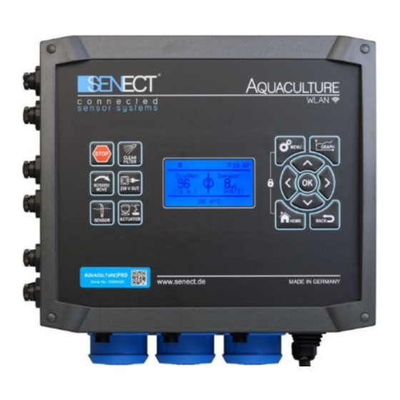
Operation Operation Display and symbols The display unit (display) shows the user important information about settings, the current operating status and the parameters measured in real time. In the top first row of the display you will find various action icons, which give the user a Figure 8 Description of the display quick overview of currently executed work processes and/or selected modes of the filter system. -
Page 29: Key Descriptions
Key descriptions Key descriptions The SENECT® control is operated using the buttons on the front panel. By pressing the MENU key, you can now make the necessary settings. Use the arrow keys and to select the corresponding menu item and confirm your selection with OK. The BACK button always takes you back one menu level, while HOME takes you back to the start screen. - Page 30 Key descriptions BACK: Use the BACK key to go back one level within the menu. HOME: Pressing the HOME button takes you from the menu to the normal view. MENU: Press the MENU button to open the menu. Here you can make your settings. GRAPH / INFO: By pressing the Graph / Info button, the past actions (history) including the time are displayed.
- Page 31 (initialization). A correct initialization is essential for the smooth functioning of your drum filter. WATER: If a SENECT solenoid valve (Type MVW-M12-SC, Art.-Nr. 3010) is connected to plug OUT 2, pressing this key will take you directly to the menu for water refill settings (see menu description).
- Page 32 Key descriptions Power fail Power failure or control unit switched off Factory setting Factory settings loaded Man. Refill. Water refill was started manually End of refill End of water refilling Timer refill Start of time-controlled refilling (timer table or interval) Sensor refill Start of sensor-controlled refilling (sensor controlled) Abort of sensor-controlled water refill (exceeding max.
-
Page 33: The Menu
Key descriptions The Menu All settings and parameters can be adjusted via the menu. The menu is structured as shown on the following page. Please note that some items in the menu are dynamic and can only be changed when certain preferences are visible. Filter Menu The menu item Filter Settings is only available for AQUACULTURE|CONTROL and FILTER|CONTROL. - Page 34 Filter Menu Submenu Operating Mode If you do not want to use the AQUACULTURE|CONTROL as filter control, select "Deactivate" here. Operating Mode Deactivate Automatic Mode Time-controlled High-Press. Cleaner However, if you use the AQUACULTURE|CONTROL to control a self-cleaning filter such as a drum or belt filter, you can select here whether the cleaning is triggered by sensor measured values (automatic mode) or by a time control (time-controlled).
- Page 35 SENSOR 3 plug. A suitable connection cable (cable cover switch DKS 5m, art. no.: 3460) can be obtained from SENECT. If the cover is opened and the switch opens its contact, any cleaning that is taking place is immediately interrupted and a connected UVC lamp (this must be defined as a UVC lamp in the sockets menu) goes out.
- Page 36 The system is automatically restarted several times and the water level and its changes are precisely evaluated. When the water levels are back in the normal range, the SENECT® Control unit automatically switches back to normal operation. Submenu Backwash Parameters In this menu item, all parameters relevant for cleaning can be set.
- Page 37 Filter Menu change only slowly, cleaning is only active when it is actually needed. In addition, this prevents too frequent cleaning, which can be particularly important when the water level in the system is low. However, if the water level falls significantly below the cleaning water level (forced flush level - this lies between the flush level and the dry-running protection level), the cleaning pause is bypassed and rinsing is carried out to prevent the water level from falling below the emergency stop level.
- Page 38 Filter Menu Submenu Eco|Mode If the Eco|Mode is activated, you can set the duration of the partial rotation here. Eco|Mode Duration Eco|Mode Submenu Alarm In the Alarm menu, you can specify which notifications you want to receive regarding filter operation.
- Page 39 Filter Menu Example: The filter cleans approximately every 5 minutes, so in 50 minutes 10 cleanings are triggered. There should be a notification when cleaning takes less than 4 minutes or more than 7 minutes. Set 40 minutes for increased cleaning and 70 minutes for less cleaning.
-
Page 40: Sensor Menu
Sensor menu Sensor menu The menu for the sensors depends on the type of sensor. Please observe the instructions in the operating manual of the respective sensor. The Sensors menu consists of the following submenus: Sensors Sensor Referencing Sensor Calibration ... - Page 41 Save Calibration Load Calibration Information Infos to Senect To do this, select which parameter you want to calibrate: Measuring channel 1 is the actual sensor, measuring channel 2 is for the integrated temperature measurement of the sensor (e.g.
- Page 42 (C1) and the operating mode used (e.g. the control unit used). Info to Senect (only with O2 Sensor): If your sensor has an error, you can send the error data directly from the control unit to SENECT to solve the problem. To do this, select Info to SENECT in the calibration menu.
- Page 43 Measuring range menu, e.g. 6000 mbar for an EDS with a measuring range up to 6 bar. Submenu Plug Name You can also assign the sensor a name with a maximum of 8 characters, which appears in the SENECT Control App, for example.
- Page 44 Alkalinity Since the CO2 calculation is dependent on temperature, the SENECT Control units offer the possibility of calculation with temperature. If a sensor with temperature measurement (e.g. TMP, CON, O2S) is connected to the control unit, the measured value of this sensor can be used for calculation (Mode: from sensor cor.).
- Page 45 Sensor menu Alternatively, a fixed temperature value can be entered (Mode: from fix value cor.). This value is entered as temperature in °C under Correction Value. Under alkalinity the alkalinity must be entered in mg/l. The display shows a conversion to °dH. Measuring Range Submenu (for pressure sensor, div.
-
Page 46: Menu Outputs And Sockets
(OUT 1 to OUT3 or OUT 6) and the three sockets (230 V OUT 1 to 230 V OUT 3), with the SENECT|ONE (OUT 1 to OUT 3) and with the SENECT|TWO (OUT 1 & 2). With the FILTER|CONTROL, only the outputs OUT1 and OUT2 and socket 2 can be assigned a function (the remaining outputs are fixed). - Page 47 Menu outputs and sockets Submenu Functions Select the function of the plug depending on the connected actuator. Available for selection: Function Filter Motor Spray Pump Circulation Pump Sensor Control Feeder Time-controlled Constant on ...
- Page 48 Alarm Handling With the "Alarm Handling" function, a warning lamp (e.g. SENECT warning lamp VIS-LED) can be connected to the actuator plug or the fault message can be forwarded to a telecommunications system or a consumer can be switched on, e.g. a ventilation pump.
- Page 49 AC motors (e.g. 230 V AC or 400 V AC) by controlling the motor speed. Please contact SENECT for suitable frequency converters for your motor.
- Page 50 Menu outputs and sockets Submenu Operating Time With the operation time you specify when the control is active. Operating Time Start time Stop time Days For example, by selecting a time from 7:00 start time to 19:00 stop time, you can prevent activation at night.
- Page 51 Menu outputs and sockets Submenu Output Coupling By means of the output coupling you can switch this output depending on another output. Output Coupling Plug Mode Off when on Off when off On when off On when on Under "Plug"...
- Page 52 Menu outputs and sockets Brief instructions: Setting the automatic feeder To use a feeder with SENECT Control units, proceed as follows: 1. Menu / Output port: Feeder / Operating time 2. Set Start and stop time: e.g. from 7:00 to 20:00 3.
- Page 53 Menu outputs and sockets Enter the maximum daily feed amount in g at a reference temperature of 16°C and the feeder will divide the total amount equally between the selected feeding times. A medium temperature is deliberately chosen to meet the requirements of as many species as possible.
- Page 54 8. Light stimulation If you use the SENECT hatchery fry feeder, you can switch on the integrated LED lamp before feeding (turn on time) and switch it off again a certain time after feeding (turn off time). If the light is to be dimmed slowly, you can specify this with the start-up duration.
- Page 55 Menu outputs and sockets Tip: If you want to add oxygen before each feeding, select the output of the sensor control (i.e. the output of the solenoid valve or aerator) and select "timed operation" as an additional function. Under "timed operation" set the mode "output coupling", so that you can set the output port to be controlled (i.e.
- Page 56 Menu outputs and sockets Submenu Output Signal In the sub-menu "Output signal", you can make settings for each output.. Output signal Output strength Start-up duration Polarity 24 V Output Min. level Max. level ...
- Page 57 Menu outputs and sockets the the output. This could be use to switch an 0-10V actuator off. In the mode Power Supply the output will provide power for an actuator that is controlled via 0-10V. If the output is switched off, the factory setting is for a level of 0 V PWM (PWM output), 0 V (0-10 V output) or 0 mA (0-20 mA output) at the output.
- Page 58 This can be useful, for example, if feeding is to be paused while working on the system. Submenu Plug name You can also give the plug a name of up to 8 characters, which then appears in the SENECT Control App. Submenu Hour meter The display of the respective output shows the operating hours, i.e.
- Page 59 Menu outputs and sockets Submenu sensor control After selecting the "Sensor control" function, the sub-menu item of the same name appears: Mode Control Parameters Sensor plug Start value Stop value Max. Duration Break time ...
- Page 60 Menu outputs and sockets The mode "Break at System Start" mode ensures that after a system start, the break time is waited for before the output is switched on for the first time. If there is a frequent power failure, this mode can ensure that not too much water is added, for example. If GroThermal is selected as control parameter, a Temperature Sensor Duo (Art.
- Page 61 Menu outputs and sockets Example: Regulation of the oxygen level In this example, the aim is to control the oxygen content to a value of over 90% with a solenoid valve that is opened when no current is applied. First of all, in "Output signal", set "Polarity"...
- Page 62 Menu outputs and sockets Interval The activation can also be controlled in intervals. In this case, the duration of the individual active phases (e.g. switch on for 5 min) is first specified. The interval time determines the time interval between the start times of the intervals (e.g. at 1 hour the water replenishment is started at 0:00, 1:00 2:00 etc.).
-
Page 63: Menu Wlan
(e.g. FIP-Box from feste-ip.net) are required to implement remote access. If you want to integrate your SENECT control into an existing WLAN network, you need a Windows (7 and higher), Android or iOS-compatible terminal device on which the SENECT... - Page 64 Menu WLAN The SENECT App is available from the Google Playstore® or the Apple App Store®. You can also find a link to download the App at www.senect.de/app. Figure 2: QR code for the link Figure 3: QR code for the...
- Page 65 WLAN symbol to the left of the time display. Tip: Have a look at our How-To #1: Connecting the Senect Control unit with a wifi network Establishing the WLAN connection of the control unit (WPS mode)
- Page 66 Menu WLAN How to add a control unit in the App 1. Select "Add device" in the settings to add a new device (control unit) to the list of your app 2. Now give the control unit a freely selectable name. If you check the box "Save name to device?", this name will be used as the device name.
- Page 67 Menu WLAN If you also want access outside your own WLAN network (full Internet capability) with the SENECT Control App, you must set up a DynDNS connection. This varies from router to router, but basically the following 3 steps are necessary: 1.
- Page 68 Menu WLAN Select the SENECT control for device or manually enter the IPv4 address of the SENECT control then click "Neue Freigabe": Make the following settings: Application: Select "Andere Anwendung" b. Bezeichnung: Choose your own name Protocol: "TCP" d. Port on device, port externally required: Port of the control unit. The port can be changed in the control unit in the menu item "WLAN"...
- Page 69 You will find this address in the settings of your Fritz!Box. Confirm this with "Add control unit". Now check the connection in your SENECT Control App - even if you are not connected to your WLAN (e.g. via mobile data)
- Page 70 This menu item is only available if an update is available. Submenu Port Number Especially if you manage several SENECT Control units in a WLAN network, you need different ports. Here you can set the port number of the control unit.
- Page 71 Menu WLAN - Subnetmask Note: If the DHCP mode is activated / deactivated, the WLAN connection is reset and the control unit tries to connect to the WLAN again. Therefore, first enter the addresses (IP, gateway, DNS and subnet mask) and then select the appropriate mode. Submenu WLAN Reset If you want to delete the saved WLAN settings, select "WLAN Reset"...
-
Page 72: System Settings Menu
System Settings menu System Settings menu Submenu Date & Time In this menu item you can select the time and date. If an Internet connection is available, your control unit can synchronise with an internet time server. You can do this under "Auto. Time" or set a time zone other than CET using UTC. - Page 73 Submenu PIN In this menu item you can enter the 4-digit numerical code required to unlock the SENECT control. Write down your PIN code and keep it safe. This PIN also gives full access to the settings and actions via the SENECT Control...
- Page 74 System Settings menu Submenu Read Only PIN If you want to set up an access with the SENECT Control App that allows the user to see only the data and receive alerts, but not to change any settings, please select a number sequence here that differs from the "normal"...
- Page 75 In order to keep the water level in the pond or basin constant and thus also to operate filters hydraulically in an optimal way, the SENECT control unit can be used in combination with a level probe (PS-300-MA or EPS-250-MA) in the pond / basin / prechamber and a SENECT solenoid valve M12 (MVW-M12-SC).
-
Page 76: Troubleshooting: What To Do If
SENECT® Control unit measures the current required to operate the filter motor during each cleaning process. If this current is too high, the SENECT® Control unit interrupts the cleaning process and thus protects against damage. Check the filter motor and also the drum or filter belt to determine the possible cause of this fault. -
Page 77: Technical Data
Technical data Technical data AQUACULTURE|CONTROL and FILTER|CONTROL Dimensions 260 x 228 x 127 mm Cable length 2,7 m Voltage 230 V AC / 50 Hz Output Power Total max. 120 W (AQC-A1-xx3-150, FC-A1-333-150) 24 V DC or 280 W (AQC-A1-xx3-300, FC-A1-333-300) 230 V Output 1 / Spraypump max. - Page 78 Power consumption < 8 W Temperature range 0°C bis +40°C Ingress protection IP 54 WLAN, Fernzugriff Dynamic DNS, Data connectivity Portweiterleitung und IPv4 * The power consumption refers to the energy consumption of the SENECT® control unit without connected consumers...
-
Page 79: Information On Correct Disposal
GmbH & Co. KG will also take care of the disposal. You can send your product to us by post or bring it directly to us (SENECT GmbH & Co. KG, An 44 – Nr. 11, D-76829 Landau). The SENECT GmbH & Co. KG is a member of the Stiftung Elektro-Altgeräte Register and for the SENECT®... -
Page 80: Notes
Notes Notes _________________________________________________________________________ _________________________________________________________________________ _________________________________________________________________________ _________________________________________________________________________ _________________________________________________________________________ _________________________________________________________________________ _________________________________________________________________________ _________________________________________________________________________ _________________________________________________________________________ _________________________________________________________________________ _________________________________________________________________________ _________________________________________________________________________ _________________________________________________________________________ _________________________________________________________________________ _________________________________________________________________________ _________________________________________________________________________ _________________________________________________________________________ _________________________________________________________________________ _________________________________________________________________________ _________________________________________________________________________ _________________________________________________________________________ _________________________________________________________________________ _________________________________________________________________________ _________________________________________________________________________ _________________________________________________________________________ _________________________________________________________________________... - Page 81 Notes _________________________________________________________________________ _________________________________________________________________________ _________________________________________________________________________ _________________________________________________________________________ _________________________________________________________________________ _________________________________________________________________________ _________________________________________________________________________ _________________________________________________________________________ _________________________________________________________________________ _________________________________________________________________________ _________________________________________________________________________ _________________________________________________________________________ _________________________________________________________________________ _________________________________________________________________________ _________________________________________________________________________ _________________________________________________________________________ _________________________________________________________________________ _________________________________________________________________________ _________________________________________________________________________ _________________________________________________________________________ _________________________________________________________________________ _________________________________________________________________________ _________________________________________________________________________ _________________________________________________________________________ _________________________________________________________________________ _________________________________________________________________________ _________________________________________________________________________...
- Page 82 Notes _________________________________________________________________________ _________________________________________________________________________ _________________________________________________________________________ _________________________________________________________________________ _________________________________________________________________________ _________________________________________________________________________ _________________________________________________________________________ _________________________________________________________________________ _________________________________________________________________________ _________________________________________________________________________ _________________________________________________________________________ _________________________________________________________________________ _________________________________________________________________________ _________________________________________________________________________ _________________________________________________________________________ _________________________________________________________________________ _________________________________________________________________________ _________________________________________________________________________ _________________________________________________________________________ _________________________________________________________________________ _________________________________________________________________________ _________________________________________________________________________ _________________________________________________________________________ _________________________________________________________________________ _________________________________________________________________________ _________________________________________________________________________...
Need help?
Do you have a question about the FILTER CONTROL 1200 and is the answer not in the manual?
Questions and answers