Table of Contents
Advertisement
Quick Links
Advertisement
Table of Contents

Related Manuals for Senect AQUACULTURE Series


Summary of Contents for Senect AQUACULTURE Series
-
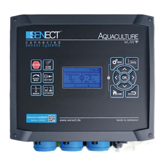
Page 2: Product Type
More information and latest software releases or documents can be downloaded from: www.senect.de Further information, application descriptions and answers to frequently asked questions can be also found on the SENECT Forum: http://forum.senect.de/phpbb/ © SENECT GmbH & Co. KG - FW 00.80... -
Page 3: Table Of Contents
Table of contents Table of contents Product type ............................2 Table of contents ............................. 3 Used symbols and wording ........................4 General Security Notes ..........................4 Intented use ............................5 Performance specification........................6 Getting started ............................7 Scope of delivery ..........................7 Installation and start-up ........................ -
Page 4: Used Symbols And Wording
Further information for the use of the device. General Security Notes The SENECT® AQUACULTURE|CONTROL is an electronic control unit developed for measuring and controlling water quality parameters and actuator like fish feeders, valves or drum filters. Since it is an electric product the common prerequisites for a safe instrument usage must be fulfilled. -
Page 5: Intented Use
Intented use The operating temperature of the device must be between 0°C and +40°C. It is not allowed to modify the SENECT® AQUACULTURE|CONTROL, to open the housing or to insert anything into the housing. If the power cable is damaged, it must be replaced by the producer or a qualified person designated by the producer to avoid potential dangers. -
Page 6: Performance Specification
(max. 8 A, 2 A, 4 A) (max. 8 A, 2 A, 4 A) Every type of SENECT sensor can be connected to the universal sensor input ports (e.g. the oxygen sensor O2S, the pH sensor XR-1 or the water level probe PS). The AQUACULTURE|CONTROL measures then the signal of the connected sensors, saves the measurements internally (up to max. -
Page 7: Getting Started
AQUACULTURE|CONTROL, the control unit can download software updates and send alarm messages. Additionally, with the SENECT Control App on an Android, Apple iOS or Windows device, the AQUACULTURE|CONTROL can be operated remotely (Internet connection with port forwarding and dynamic DNS necessary, for more details see chapter WLAN). - Page 8 Getting started Fig. 1: Wall mounting parts and dimensions of the drill holes for the mounting of the AQUACULTURE|CONTROL. Fig. 2: Sensor and actuator ports of the AQUACULTURE|CONTROL Pro. The AQUACULTURE|CONTROL Basic is equipped without the upper row (SENSOR 4-6 and OUT 4-6).
-
Page 9: Using The Aquaculture|Control To Switch Outputs As A Function Of Sensor Measurements
Getting started Fig. 3: View from the bottom side of the AQUACULTURE|CONTROL. Using the AQUACULTURE|CONTROL to switch outputs as a function of sensor measurements Which sensors, which actuators and how the cables are conneced depend strongly on your application. In general, you can follow these steps: 1. - Page 10 Getting started Application example: Oxygen control In this example, the oxygen sensor O2S is connected to SENSOR 1 and the „normally opened“ solenoid valve (Type: MVO-M7-SC, Art. No.: 3020) is plugged into actuator plug OUT 1. („Normally open“ is selected here, that in case of a power shutdown the valve opens automatically and the fish still get oxygen.) The desired oxygen level should be over 95% and if 100% are reached, the addition of oxygen shall be stopped.
-
Page 11: Controlling The Drum Filter With The Aquaculture|Control
If your filter is equipped with a case or cover proximity switch, you can connect it to SENSOR 3. If you do not have a suitable plug at your switch, you can order the proper plug from SENECT or your dealer. - Page 12 Getting started Fig. 4: Connecting an open channel drum filter and a boxed drum filter. Please note that the filter motors here are controlled by the high-power acuator output port OUT 3.
- Page 13 AQUACULTURE |CONTROL and the filter motor is necessary. SENECT offers fully parametrized and wired VFDs. The green labelled actuator cable from the VFD must be connected to one the actuator output ports, e.g. OUT 1.
- Page 14 Getting started Fig. 5: Connecting a drum filter via a variable frequency drive. Note: Select the function “filter motor” for the corresponding actuator output port (here OUT 1) and select the additional function “variable frequency drive”. 4.) Connecting the spray and circulation pump pumps correctly installed,...
- Page 15 Getting started Fig. 6 Sketch showing the general two hydraulic systems in which drum filter are operated. STARTING THE SYSTEM Switch the AQUACULTURE|CONTROL on with the ON/OFF Switch at the bottom (Fig. 3). By pressing the button MENU, you can configure all necessary settings. With the cursor buttons ...
-
Page 16: Using The Aquaculture|Control To Switch Outputs As A Function Of Sensor Measurements - Short Version
Getting started Output ports / Plug X the function „Filter Motor” and the additional function “Var. Frequency Dri”. To assign a function to the water level sensor(s), select in the menu Sensors / S X / Position to the location where the sensor is mounted. Is it in front of the drum, select “Pre-chamber”, and is it mounted behind the drum, select “Filter-chamber”. -
Page 17: Controlling The Drum Filter With The Aquaculture|Control - Short Version
Getting started Select in the Menu / Output ports or Menu / 230 V Plug the output, at which the corresponding actuator (e.g. aerator, valve) will be plugged and select the desired function. If you want to switch the output in relation to sensor readings, select „Sensor Control“. - Page 18 Getting started Check the water level. If the water level is correct, set it to “0 cm” in the menu / Sensors Sx: PS 3m / Sensor referencing. Now, your system is ready for operation. Please note that the filter backwash water levels refer to the referenced water level while the alarm settings of the sensor refer to the absolute water level.
-
Page 19: Operation
Operation Operation Display and symbols On the display, you´ll find information about filter operation, current measurements and the status of the instrument. The upper row shows you action symbols, which display Fig. 8: The display of the AQUACULTURE|CONTROL. the current running actions or modes of operation. -
Page 20: Buttons And Menu
Operation Buttons and menu The AQUACULTURE|CONTROL is operated by the user via the buttons on the front. With the navigation buttons (, , , , BACK and HOME) you can navigate through the menu. To change the displayed view from the filter status to the sensor values (the number in the center circle show the SENSOR plug number) press ... - Page 21 Operation while with pressing and you can change the temporal scale of the x axis (e.g. 1 hour, 1 day). Here you can also find the history recordings or device or WLAN information. Lock: By pressing the buttons MENU and HOME simulatanously, the lock is active. To unlock the keypad, you have to enter the Pin Code.
-
Page 22: The Menu
The Menu Entry Description Timer refill Start of time-controlled refilling Sensor refill Start of sensor-controlled refilling (time table) Interv. refill Start of time-controlled refilling (interval) Abort sensorc. Abort of sensor-controlled water refill (exceeding max. time) Timer on Timer controlled output was switched on Timer off Timer controlled output was switched off Sen.Reg.on... - Page 23 The Menu Filter Settings Filter Mode Gravity System Pumped System Operating Mode Deactivate Automatic Mode Time-controlled High-Press. Cleaner Extras Deactivate Dynamic|Mode Eco|Mode Cover Sw. DF Cover Sw. EBF Dry run Prot. Off Dry run pro. pump sump. Water Level Flush Level Dry run Protection 1 Dry run Protection 2 (only pumped system) Backwash Parameter...
- Page 24 The Menu Sensors S1: O2S Name (Example Oxygen Sensor O2S) Sensor Calibration Channel 1 (O2 % a. s.) Calibration Point 1 Calibration Point 2 Factory settings Channel 2 (Temperature) Calibration Point 1 Calibration Point 2 Information Alarm Threshold Lower Threshold (O2) Upper Threshold (O2) Hysteresis (O2) Lower Threshold (°C)
- Page 25 The Menu Output ports / 230 V Plug Plug 1 Function Filter Motor Spray Pump Circulation Pump Sensor Control Feeder Time-controlled Constant on UVC Lamp Alarm Additional function Alarm Coupling Output Coupling Time-controlled Operating Time Start Time Stop Time Alarm Handling Turn output off Turn output on Output Coupling...
-
Page 26: Filter Settings
The Menu WLAN Information WLAN menu WLAN Configuration Start Update Port Number DHCP Mode DHCP Mode IP Address Gateway Subnetmask WLAN reset System Settings Date & Time System menu Time Date Auto. Time Language Alarm Recall Factory Settings Device Information Backup Settings Filter settings Here you can configure all relevant settings for the filter operation. - Page 27 The Menu Here you can select the activation of extra functions. 1. Dynamic|Mode: The Dynamic|Mode is a special algorithm which leads to a more stable clogging-induced control of the backwashing. With this mode, the backwash water level is continuously corrected for changes in the water level. Please note, that the backwashing is then not at exactly the specified backwash water level.
- Page 28 The Menu Backwash Parameter Here you can set all relevant parameters for the filter cleaning. Backwash Duration The backwash duration defines the time of one cleaning cycle. Choose the flush time so that the drum is rotated at least one time completely. ...
- Page 29 The Menu Intensive cleaning Since the filter mesh can clog regularly by biofouling or calcareous crusts, the FITLER|CONTROL initiates in regular intervals an intensive cleaning mode where by a reduction of the motor speed the filter mesh is cleaned more intensively. ...
-
Page 30: Sensor Menu
The Menu Sensor Menu To change the settings of the connected sensors, please select here the sensor. Please refer to the manuals of each sensor. The entire menu is dynamic and may change depending on the sensor connected. Sensors (Shortcut: Button SENSOR) To change the sensor settings or to calibrate the sensors, select in the menu under Sensors the desired sensor (plug). - Page 31 Plug name With plug name you can give the sensor a name of max. 8 characters, which will be displayed in the SENECT Control App. Change zero-point If the sensor is used for refilling, you can change the zero-point (reference level) so that it is shiftet by the manually set level.
-
Page 32: Menu Output Ports And 230 V Ac Plugs
SENECT Control App. Salinity correction Since the oxygen saturation concentration depends on the salinity of the water, the SENECT control can correct for the effect of salinity. Therefore, you can either enter a specific salinity (Mode: Correction value) or connect a conductivity sensor (Mode: Sensor corrected), which calculates the salinity and the correction based on conductivity measurements. -
Page 33: Description Of The Major Output Functions
The Menu Plug 1 to 6 / 230 V Plug 1 to 3 Please note that 230 V plugs can only be switched on and off while the actuator output ports can also control the output strength (e.g. only 75% of the output signal strength). ... - Page 34 The Menu Sensor Control To switch output ports in relation to the signal of a connected sensor, you have to select the “sensor control” function. Select under “Control Parameter” the signal to which the output shall respond, e.g. % a.s. for the oxygen saturation.
- Page 35 Enter in this menu item the concentration of oxygen below which the feeding is cancelled. Note, that it is necessary that a SENECT oxygen sensor O2S needs to be connected and that this sensor is selected under “plug”.
- Page 36 (which refers to 16°C) according to the measured temperature. Light stimulation: Some fish feeders from SENECT are equipped with LEDs to attract the fish to the location of the feeder prior to the feeding. You can select in this menu item, how long before the feeding (turn on time) and how long after feeding (turn off time) the LEDs should be switched on.
-
Page 37: Additional Functions
Does one sensor value exceeds the upper threshold or falls below the lower threshold, a alarm state is activated and all outputs with alarm coupling or outputs with the function „alarm“ react. Here, you can for example connect an alarm lamp directly to the output (e.g. the SENECT Alarm lamp VIS-LED). - Page 38 The Menu At first, you have to select the output port, to which the additional function is related under the item “plug”. This one is the output, which gives the information. In the next step, you can select the logic mode, how the output should respond to the “information giving output”.
- Page 39 (VFD) with a 4-20 mA signal and the activation with the 24 V DC signal. This function is designed to control 230 V AC and 380 V AC filter motors. SENECT offers VFDs. Output signal The output signal can be configured in three different ways: 1.
-
Page 40: Menu Wlan
This function can be for instance be used to estimate exchange intervals of actuators, e.g. UVC lamps. Menu WLAN Additional information and help with respect to the wifi connectivity can be found on the SENECT forum under: http://forum.senect.de/phpbb/ Fig. 11: QR Code with a link to the SENECT forum. - Page 41 If you want to integrate your AQUACULTURE|CONTROL in an existing WLAN- network, you need a Windows (Version 7 or higher), Android or iOS-based device on which the SENECT Control App is installed. The SENECT Control App is available in the Google Playstore or the Apple App Store.
- Page 42 AQUACULTURE|CONTROL´s display. Embedding the AQUACULTURE|CONTROL unit in your SENECT Control App: 1. Open the SENECT Control App and press the button “Add control unit” 2. Choose an individual name for the control unit and enter its IP address (you´ll find it under Menu/WLAN/Information).
- Page 43 2. Click on “Internet” to “Freigaben” and select to add a new device (“Gerät für Freigabe hinzufügen”) 3. Select at “Gerät” the AQUACULTURE|CONTROL. It will be labelled with “Senect- 101xxxxx”, where the x denote the serial number of your AQUACULTURE|CONTROL.
- Page 44 5. Select as „Schema“: „http://“ and type in the port number of the AQUACULTURE|CONTROL (30000 as factory setting, if you use several SENECT control units, each single one must have its own port number. You can change it in the...
- Page 45 DNS address of the control unit. You need this address in the SENECT Control App to establish the remote access. To enable the remote access with the SENECT Control App, you need to go to the WLAN settings of the control unit in your App. Press therefore the button “settings”.
-
Page 46: Menu System Settings
Port number Under factory settings, the port number of your control unit is 30000. If you are using several SENECT control units, every units needs its own port number. Here you can change it e.g. to 30001. DHCP For some routers, it is necessary to switch DHCP off. - Page 47 The Menu Factory settings If you want to reset the AQUACULTURE|CONTROL, choose „Factory settings” and confirm with yes. Warning: All settings and saved parameters are deleted! Alarm recall In case of an alarming, the warning by the push service and email can be repeated, if the condition of the alarm remains.
-
Page 48: Technical Data
Do not throw the product in the casual litter bin. Make sure you are informed about the local disposal regulations and dispose your product accordingly. Alternatively, you can also send the product back to the producer. The SENECT GmbH & Co. KG is member of the Stiftung Elektro-Altgeräte Register and the products are registered (WEEE-Reg.-Nr.: DE37193510). Guarantee Please check at delivery of your AQUACULTURE|CONTROL, that all parts are delivered completely and that they function correctly. - Page 49 Guarantee describe your claim as detailed as possible so that we can provide a solution as fast as possible. The following details must be given to guarantee a fast support: Detailed error or claim description Information about the use of the AQUACULTURE|CONTROL (e.g. system type, filter) ...
Need help?
Do you have a question about the AQUACULTURE Series and is the answer not in the manual?
Questions and answers