Table of Contents
Advertisement
Quick Links
Operating Instructions & Parts Manual
Please read and save these instructions. Read carefully before attempting to assemble, install, operate or maintain the product described. Protect yourself
and others by observing all safety information. Failure to comply with instructions could result in personal injury and/or property damage! Retain instructions
for future reference.
Westward Heavy Duty Wheel Dolly
Description
Westward heavy duty wheel dolly is designed to remove, transport and replace tire and
wheel assemblies on trucks, buses and trailers. It is a labor saving device useful in auto
shops, bus barns and fleet service. This wheel dolly is designed to meet applicable
ANSI/PALD Standards.
Specifications
Overall Size
Model
Capacity
(L X W X H)
5ML74A
3/4 Ton
45-
/
"
1
X
8
(1500 Lbs)
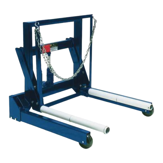
Angle Frame
Roller
Hydraulic Unit
Figure 1 - Wheel Dolly Components
General Safety Information
Read and understand
all warnings and
instructional material provided on and with
this product. Do not exceed rated capacity.
Thoroughly familiarize yourself with this
product before use. Use only on smooth
hard, level surfaces capable of sustaining
the load. Before moving, lower the load to
the lowest possible point and assure that
the load is centered and secured with a
load restraint device. Apply load as close
to the vertical position of the lifting
member as possible. No alterations shall
be made to this product. Do not use this
device for any purpose other than that for
which it is intended. Failure to heed this
warning may result in severe, injury as
well as property damage.
SHI 021
Printed in China
11/09
®
Rollers
Distance
39-
/
"
34
/
"
26"
1
X
5
2
8
ASSEMBLY
Refer to Figure 2 on page 2
1. Attach leg assemblies (Ref. No. 2) to
main frame (Ref. No. 1) using
M12x1.75x70L &
M12x1.75x120L bolts, M12x1.75 nuts
& M12x3t washers (Ref. Nos. 3, 15, 4
& 5).
2. Install caps (Ref. No. 17) to cover the
holes on the main frame (Ref. No. 1).
3. Loosen all four of the M12x1.75x70L
bolts (Ref. No. 8) and tighten the
M10x1.5x60L bolts (Ref. No. 11) to
expand the roller insert hole.
Note: Do not overtighten the bolts (Ref.
Lifting
Tilt
Range
Degree
2-
/
" ~ 8-
/
"
5°
1
3
2
8
Chain
Main Frame
Load Leveler
with Caster
(not shown)
Front Wheel
No. 11). Adjust bolt's tightness until it is
expanded enough for accepting the
roller (Ref. No. 6).
4. Slide roller (Ref. No. 6) into the roller
insert hole on frame (Ref. No. 7) until it
is aligned with the edge of the hole.
5. Loosen the M10x1.5x60L bolts (Ref.
No. 11) and tighten all the
M12x1.75x70L bolts (Ref. No. 8) to
secure the roller onto the frame.
6. Attach the frame (Ref. No 7) to main
frame (Ref. No. 1) using the pin, c-clip
and roller. (Ref. No. 12, 13 & 14).
7. Install hydraulic unit (Ref. No. 18) in
between the frame and main frame
(Ref. No. 7 & 1).
8. Attach hooks (Ref. No. 21) to chain
(Ref. No. 20).
9. Attach one end of hook (Ref. No. 21)
through angle frame hole and attach
another hook to the other hole.
BEFORE USE
1. Inspect before each use. Do not use if
bent, broken, leaking or cracked
components are noted. Ensure that
casters, rollers and lift arm moves
freely. Check and tighten any loose
assemblies.
2. Verify that the product and the
application are compatible.
3. Read, understand and follow vehicle
manufacturer's recommended tire
change procedures.
4. With jack in fully lowered position,
locate and remove oil filler plug. This
purges the hydraulic system of
pressurized air trapped in reservoir.
Check fluid level. Proper level is even
with filler plug hole.
5. Reinstall oil filler plug.
HOW TO USE
1. Set emergency brake, chock tires of
diagonally opposed wheel(s) in both
directions AND take every precaution
necessary to ensure setup is stable
and prevent inadvertent vehicle
5ML74A
Advertisement
Table of Contents

Related Manuals for Westward 5ML74A


Summary of Contents for Westward 5ML74A
- Page 1 No. 11). Adjust bolt’s tightness until it is expanded enough for accepting the Westward heavy duty wheel dolly is designed to remove, transport and replace tire and roller (Ref. No. 6). wheel assemblies on trucks, buses and trailers. It is a labor saving device useful in auto shops, bus barns and fleet service.
- Page 2 5ML74A Westward Operating Instructions and Parts Manual Westward Heavy Duty Wheel Dolly ® General Safety Information use it as a structure support or other MAINTENANCE (Continued) means. Use the main frame to push or Periodically check jack fluid level. Level pull while installing or removing the tire/ movement.
- Page 3 1657 Shermer Road Northbrook, IL 60065-3074 U.S.A. Figure 3 — Repair Parts Illustration Repair Parts List Reference Part Number For Model: Number Description 5ML74A (3/4 Ton or 1500 Lbs) Quantity Spring Pin 5420-04030-000 Chain 4200-03004-000 Retaining Ring "C" 5304-00016-000 T540-02002-000...
- Page 4 WESTWARD ONE-YEAR LIMITED WARRANTY. Heavy Duty Wheel Dolly, covered in this manual, is warranted by Westward to the original user against defects in workmanship or materials under normal use for one year after date of purchase. Any part which is determined to be defective in material or workmanship and returned to an authorized service location, as Westward designates, shipping costs prepaid, will be, as the exclusive remedy, repaired or replaced at Westward's option.
Need help?
Do you have a question about the 5ML74A and is the answer not in the manual?
Questions and answers