Table of Contents
Advertisement
Quick Links
Advertisement
Table of Contents

Related Manuals for APT 8KW


Summary of Contents for APT 8KW
- Page 1 User Manual SOLAR INVERTER / CHARGER Version: 1.0...
-
Page 2: Table Of Contents
Table Of Contents 1.About This ......................1 1.1 Manual Purpose ......................1 1.2 Scope ..........................1 2.Safety Instructions ....................1 3. Introduction ......................1 3.1 Features .......................... 1 3.2 Basic System Architecture ....................2 ... -
Page 3: About This
1.About This 1.1 Manual Purpose This manual describes the assembly, installation, operation and troubleshooting of this unit. Please read this manual carefully before installations and operations. Keep this manual for future reference. 1.2 Scope This manual provides safety and installation guidelines as well as information on tools and wiring. 2.Safety Instructions WARNING: This chapter contains important safety and operating instructions. -
Page 4: Basic System Architecture
3.2 Basic System Architecture The following illustration shows basic application for this unit. It also required the following devices to have a complete running system: Generator or Utility mains. PV modules Consult with your system integrator for other possible system architectures depending on your requirements. This inverter can power various appliances in home or office environment, including motor-type appliances such as tube light, fan, refrigerator and air conditioners. -
Page 5: Product Overview
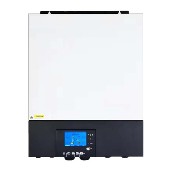
3.3 Product Overview NOTE: The following picture is only a schematic diagram of the equipment .If the actual chassis does not conform to the schematic due to a structural upgrade, it is subject to prior notice. 1: Remote LCD module communication port 2: Generator dry contact 3: USB port 4: RS485 port/CAN port... -
Page 6: Installation
4. Installation 4.1 Unpacking And Inspection Before installation, please inspect the unit. Be sure that nothing inside the package is damaged. You should have received the following items inside of package: The inverter x1 User manual x 1 RS232 Communication cable x 1 USB Communication cable x 1 Parallel communication cable x 1(No parallel machine ,No need) Current sharing cable x 1 (No parallel machine ,No need) -
Page 7: Battery Connection
Install the unit by screwing four screws. It’s recommended to use M4 or M5 screws. 4.4 Battery Connection CAUTION: For safety operation and regulation compliance, it’s requested to install a separate DC over-current protector or disconnect device between battery and inverter. It may not be requested to have a disconnect device in some applications, however, it’s still requested to have over-current protection installed. - Page 8 48VDC battery connection diagram 3. Insert the ring terminal of battery cable flatly into battery connector of inverter and make sure the nuts are tightened with torque of 5 Nm. Make sure polarity at both the battery and the inverter/charge is correctly connected and ring terminals are tightly screwed to the battery terminals.
-
Page 9: Ac Input/Output Connection
4.5 AC Input/output Connection CAUTION!! Before connecting to AC input power source, please install a separate AC breaker between inverter and AC input power source. This will ensure the inverter can be securely disconnected during maintenance and fully protected from over current of AC input. CAUTION!! Please refer to the input and output screen on the machine before wiring, make sure correct wiring. -
Page 10: Pv Connection
5. Then, insert AC output wires according to polarities indicated on terminal block and tighten terminal screws. Be sure to connect PE protective conductor ( ) first. →Ground (yellow-green) L→LINE (brown or black) N→Neutral (blue) 6. Make sure the wires are securely connected. CAUTION: Important Be sure to connect AC wires with correct polarity. - Page 11 Components for PV connectors and Tools: Female connector housing Female terminal Male connector housing Male terminal Crimping tool and spanner Prepare the cable and follow the connector assembly process: Strip one cable 8 mm on both end sides and be careful NOT to nick conductors. Insert striped cable into female terminal and crimp female terminal as shown below.
- Page 12 Step 4: Check correct polarity of connection cable from PV modules and PV input connectors. Then, connect positive pole (+) of connection cable to positive pole (+) of PV input connector. Connect negative pole (-) of connection cable to negative pole (-) of PV input connector. WARNING! For safety and efficiency, it's very important to use appropriate cables for PV module connection.
- Page 13 Recommended Panel Configuration When selecting proper PV modules, please be sure to consider the following parameters: 1. Open circuit Voltage (Voc) of PV modules not to exceed maximum PV array open circuit voltage of the inverter. 2. Open circuit Voltage (Voc) of PV modules should be higher than the start-up voltage. INVERTER MODEL Max.
-
Page 14: Final Assembly
4.7 Final Assembly After connecting all wirings, re-connect three cables and then put bottom cover back by screwing two screws as shown below. 4.8 RS232/USB Communication Connection Please download software “SolarPower” from the official website. When the inverter is connected to the computer, the following interface will be displayed. -
Page 15: Dry Contact Signal
4.10 Dry Contact Signal There is one dry contact (3A250VAC) available on the rear panel. It could be used to deliver signal to external device when battery reaches warning level. Unit Status Condition NC & C C & NO Power Off Unit is off and no output is powered Open Close... -
Page 16: Operation
5. Operation 5.1 Power ON/OFF Once the unit has been properly installed and the batteries are connected well, simply press On/Off switch(located on the button of the case) to turn on the unit. 5.2 Operation And Display Panel The operation and display panel, shown in below chart, is on the front panel of the inverter. It includes three indicators, four function keys and a LCD display, indicating the operating status and input/output power information. -
Page 17: Lcd Display Icons
5.3 LCD Display Icons Grid PV1/PV2 Icon Description operation time Operation information include fault and warning code Input voltage ,current and power information Output voltage ,current and power information PV input voltage , PV input current ,PV input power information NOTE: the information of PV1 and PV2 is automatically switched every 3 seconds Battery voltage ,current and power information Indicates the DC/AC inverter circuit is working... -
Page 18: Lcd Setting
Inverter working status Battery mode run status: Bat inv Utility mode run status: AC Bypass PV +Utility mode run status: PV+AC Volume icon LCD Version , Inverter Version , Mppt Version , Machine Type This button includes generation, event, help language,... - Page 19 item menu description Language Default: English AC :(default) AC will provide power to the loads as the priority, solar charging the battery. When solar energy is insufficient, AC and solar energy charge the battery at the same time. When AC is unavailable, it will be powered by solar energy or batteries.
- Page 20 220V(option) 230V(default) 240V(option) Output 50HZ(default) 60HZ(option) 1.Lead acid battery(default) Battery 2.Lithium(option) 3.No Bat: no battery(option) 4.User: (option) 4.1. If “User-Defined” is selected, Bulk charging voltage and Floating charging voltage, setting range: 48.0V to 60V, Increment of each click is 0.1V. 4.2.
- Page 21 After the communication connection between the inverter and the lithium battery is successful, you can view the information of the lithium battery Battery 1.discharge current limited disable(default) 2. setting range :10A to 200A setting increase or decrease of 5A . NOTE: if you work in “Solar”...
- Page 22 Stand-alone running mode Single-phase parallel mode Note: This setting is only available when the inverter is in standby mode (Switch off). Parallel Three Phase: 1.if users need three-phase parallel ,each device must be set to A/B/C separately. 2.Three-phase parallel needs at least three device to do three-phase parallel run.
- Page 23 Grid OnGrid: enable Alternate menu Beep Enable(default) Other Beep disable: mute Factory reset: disable(default) Other Factory reset: enable, all parameters are restored to their default values...
- Page 24 Generation:the data in the picture is for reference only. Event:you can view the running record of the device. History Help:you can view fault and warning codes. LCD display version Inverter control version About Mppt control version Machine type...
-
Page 25: Parallel Installation Guide
6. Parallel Installation Guide 6.1Parallel Operation Cable 1. Recommended battery cable and terminal size for each inverter: Ring Terminal Typical Battery Model Wire Size Torque Cable mm2 Dimensions Length Amperage capacity value D (mm) L (mm) 100AH 1AWG 190.5A 5 Nm 200AH 1/0AWG WARNING: Be sure the length of all battery cables is the same. -
Page 26: Single-Phase Parallel Operation Cable Connection
6.3 Single-phase Parallel Operation Cable Connection 1.Two inverters in parallel: Power Connection: NOTE: The following picture is only a schematic diagram of the equipment .If the actual chassis does not conform to the schematic due to a structural upgrade, it is subject to prior notice. Communication Connection 2.Three inverters in parallel:... - Page 27 Communication Connection 3.Four inverters in parallel: Power Connection: NOTE: The following picture is only a schematic diagram of the equipment .If the actual chassis does not conform to the schematic due to a structural upgrade, it is subject to prior notice. Communication Connection 4.Five inverters in parallel:...
-
Page 28: Matters Needing Attention In Three-Phase Parallel Operation
Communication Connection 5.Six inverters in parallel: Power Connection: NOTE: The following picture is only a schematic diagram of the equipment .If the actual chassis does not conform to the schematic due to a structural upgrade, it is subject to prior notice. Communication Connection 6.4 Matters Needing Attention In Three-phase Parallel Operation 1. -
Page 29: Three-Phase Parallel Operation Cable Connection
6.5 Three-phase Parallel Operation Cable Connection 1. One inverters in each phase: Power Connection: NOTE: The following picture is only a schematic diagram of the equipment .If the actual chassis does not conform to the schematic due to a structural upgrade, it is subject to prior notice. NOTE:P1: A-phase, P2: B-phase, P3: C-phase. - Page 30 2. Two inverters in each phase: Power Connection: NOTE: The following picture is only a schematic diagram of the equipment .If the actual chassis does not conform to the schematic due to a structural upgrade, it is subject to prior notice. NOTE:P1: A-phase, P2: B-phase, P3: C-phase.
- Page 31 Communication Connection 4.Three inverters in one phase, two inverters in second phase and one inverter for the third phase: Power Connection: NOTE: The following picture is only a schematic diagram of the equipment .If the actual chassis does not conform to the schematic due to a structural upgrade, it is subject to prior notice. NOTE:P1: A-phase, P2: B-phase, P3: C-phase.
- Page 32 5. Three inverters in one phase and only one inverter for the remaining two phases: Power Connection: NOTE: The following picture is only a schematic diagram of the equipment .If the actual chassis does not conform to the schematic due to a structural upgrade, it is subject to prior notice. NOTE:P1: A-phase, P2: B-phase, P3: C-phase.
- Page 33 Communication Connection 7.Two inverters in one phase and only one inverter for the remaining phases: Power Connection: NOTE: The following picture is only a schematic diagram of the equipment .If the actual chassis does not conform to the schematic due to a structural upgrade, it is subject to prior notice. NOTE:P1: A-phase, P2: B-phase, P3: C-phase.
-
Page 34: Faults Code
7. Faults Code Fault Code Fault Event Fan is locked Over temperature Battery voltage is too high Battery voltage is too low Output short circuited. Output voltage is too high. Overload time out Bus voltage is too high Bus soft start failed PV over temperature Bus voltage is too low Inverter soft start failed... -
Page 35: Parallel Faults Code
9. Parallel Faults Code Fault Code Fault Event Power feedback protection Firmware version inconsistent Current sharing fault Output voltage different CAN fault Host loss Synchronization loss Battery voltage detected different AC input voltage and frequency detected different AC output current unbalance AC output mode setting is different... -
Page 36: Trouble Shooting
10. Trouble Shooting Problem LCD/LED/Buzzer Possible cause What to do Unit shuts down LCD/LED and buzzer will be The battery voltage is too 1.Re-charge battery. automatically during active then complete off 2. Replace battery start up process 1.Contact repair center 1.The battery voltage is too No response for replacing the fuse. - Page 37 return to the maintenance Fault code 08/09/12/53/57 Internal fault of inverter center Remove abnormal load or Fault code 10 Over current or surge check PV input The configuration of the solar panel is higher remove the excess solar Fault code 11 than the PV input panels voltage required by the...
- Page 38 Fault code 80 CAN data loss 1.Check if communication Host data loss(only for cables are connected well and Fault code 81 three-phase parallel) restart the inverter 2. If the problem remains, please contact your installer. Synchronization data Fault code 82 loss 1.Make sure all inverters share same groups of batteries...
-
Page 39: Specifications
11. Specifications 11.1 Line Mode Specifications MODEL 8KW48Vdc Input Voltage Waveform Sinusoidal (utility or generator) Nominal Input Voltage 230Vac 170Vac±7Vac (narrow range) Low Loss Voltage 90Vac±7Vac (wide range) 180Vac±7Vac (narrow range) Low Loss Return Voltage 100Vac±7Vac (narrow range) High Loss Voltage 280Vac±7Vac High Loss Return Voltage 270Vac±7Vac... -
Page 40: Inverter Mode Specifications
11.2 Inverter Mode Specifications MODEL 8KW48Vdc Rated Output Power 8000W Output Voltage Waveform Pure Sine Wave Output Voltage Regulation 230Vac±5% Output Frequency 60Hz or 50Hz Max. peak Efficiency Overload Protection 5s@≥150% load; 10s@110%~150% load Surge Capacity 2* rated power for 5 seconds Low DC Cut-off Voltage 42Vdc Nominal DC Input Voltage... -
Page 41: Charge Mode Specifications
11.3 Charge Mode Specifications Utility Charging Mode MODEL 8KW48Vdc Charging Current 120A @ Nominal Input Voltage Flooded Battery 58.4Vdc Bulk Charging Voltage AGM / Gel Battery 56.4Vdc Floating Charging Voltage 54.0Vdc Overcharge Protection 60.0Vdc Charging Algorithm 3-Step Charging Curve Solar Input MODEL 8KW48Vdc Max. -
Page 42: General Specifications
11.4 General Specifications MODEL 8KW48Vdc Safety Certification Operating Temperature Range -10°C to 50°C Storage temperature -15°C~ 60°C Humidity 5% to 95% Relative Humidity (Non-condensing) Dimension 554*420*153 (L*W*H), mm Net Weight, kg 18.4 12. Installation Dimension Drawing (unit:mm) NOTE: The following picture is only a schematic diagram of the equipment .If the actual chassis does not conform to the schematic due to a structural upgrade, it is subject to prior notice. - Page 43 614.C0525-00...
Need help?
Do you have a question about the 8KW and is the answer not in the manual?
Questions and answers