Table of Contents
Advertisement
Quick Links
Quick Start Guide
CLOCKED SEQUENTIAL
CONTROL MODULE 1027
Legendary 2500 Series 8-Position Step
Sequencer Module for Eurorack
(2)
(4)
(5)
(6)
(7)
(8)
(9)
(10)
(11)
(12)
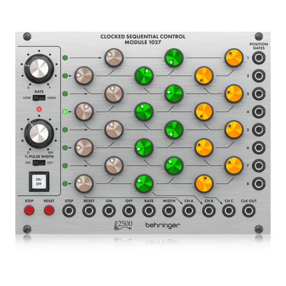
CH A / CH B / CH C SEQUENCER COLUMNS – Use the
(1)
knobs to set the control voltage output for each step.
Each column sends out control voltages via that channel's
respective CH A / CH B / CH C output jack.
STEP LEDs – Each LED lights to indicate its respective
(2)
sequencer step is active.
Position Gates – Each of these output jacks sends out a
(3)
gate signal for its respective sequence step via cables with
3.5 mm TS connectors. These 8 gate output signals are
also available via the 12-pin GATE OUT LINK CONNECTOR
located on the module underside. This 12-pin connector
can connect to and trigger other compatible modules,
such as the MIX-SEQUENCER MODULE 1050, via a 12-pin
ribbon connector.
RATE – This knob controls the step speed at which the
(4)
sequencer moves from step to step. The knob operates
in two overall frequency ranges determined by the
LOW/HIGH switch.
LOW/HIGH – Use this sliding switch to set whether the
(5)
RATE knob operates in a lower-frequency (LOW) or
higher-frequency (HIGH) range.
V 1.0
Downloaded from
ManualsNet.com
(1)
(13) (14)(15)(16)(17)
(18) (19)
search engine
% PULSE WIDTH – Select between width settings
(6)
for the rectangular waveform ranging from 5% to 95%
duty cycle. The PULSE WIDTH control operates on the
CLK OUT jack only, making this control very useful for
triggering other modules such as envelope generators,
and so on.
INT/EXT – Use this switch to select between internal (INT)
(7)
or external (EXT) pulse width control voltage. When EXT
is selected, the % PULSE WIDTH control knob is disabled.
ON /OFF – This button starts or stops the sequence with a
(8)
(3)
manual button push.
STEP – Press this button to manually progress to the next
(9)
sequencer step.
RESET – Press this button to manually restart the
(10)
sequence at step 1.
STEP – Use this jack to route external trigger signals for
(11)
the STEP button into the module via cables with 3.5 mm
TS connectors.
RESET – Use this jack to route external trigger signals for
(12)
the RESET button into the module via cables with 3.5 mm
TS connectors.
ON – Use this jack to route external trigger signals to
(13)
enable the step counter into the module via cables with
3.5 mm TS connectors.
(20)
OFF – Use this jack to route external trigger signals to
(14)
disable the step counter into the module via cables with
3.5 mm TS connectors.
RATE – Use this jack to route in external control voltage
(15)
signals for the sequencer's step speed (usually controlled
by the RATE knob) via cables with 3.5 mm TS connectors.
WIDTH – This jack allows control voltage and modulation
(16)
signals for the rectangular waveform to be routed in via
cables with 3.5 mm TS connectors.
CH A – This jack sends out control voltage signals for
(17)
the CH A sequencer column via cables with 3.5 mm
TS connectors.
CH B – This jack sends out control voltage signals for
(18)
the CH B sequencer column via cables with 3.5 mm
TS connectors.
CH C – This jack sends out control voltage signals for
(19)
the CH C sequencer column via cables with 3.5 mm
TS connectors.
CLK OUT – Use this jack to export the internally generated
(20)
clock signal via cables with 3.5 mm TS connectors.
The internal clock produces a gate pulse every time
the sequencer steps, and the gate pulse's width can be
adjusted using the % PULSE WIDTH control or via the
WIDTH control jack.
Advertisement
Table of Contents

Subscribe to Our Youtube Channel
Related Manuals for Behringer 1027


Summary of Contents for Behringer 1027
- Page 1 CLOCKED SEQUENTIAL % PULSE WIDTH – Select between width settings for the rectangular waveform ranging from 5% to 95% CONTROL MODULE 1027 duty cycle. The PULSE WIDTH control operates on the CLK OUT jack only, making this control very useful for...
- Page 2 DC coupled Impedance 100 KΩ, unbalanced Maximum input level 10 V The CLOCKED SEQUENTIAL CONTROL MODULE 1027 module comes Minimum switching 2.5 V, trigger with the required power cable for connecting to a standard threshold Eurorack power supply system. Follow these steps to connect power to the module.
- Page 3 All trademarks are the Impedance 1 KΩ, unbalanced property of their respective owners. Midas, Klark Teknik, Lab Gruppen, Lake, Tannoy, Turbosound, TC Electronic, TC Helicon, Behringer, Bugera, Auratone Maximum Output level and Coolaudio are trademarks or registered trademarks of Music Tribe Controls Global Brands Ltd.
Need help?
Do you have a question about the 1027 and is the answer not in the manual?
Questions and answers