Table of Contents
Advertisement
Quick Links
Advertisement
Table of Contents

Subscribe to Our Youtube Channel
Summary of Contents for AQUA FORTE SC997
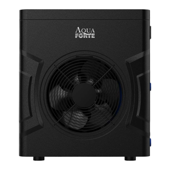
- Page 1 Mini Heat Pump for Swimming Pool User and Service Manual...
-
Page 3: Table Of Contents
Contents I. Unit Parameters................................ 1 II. System Specification...............................4 Specification..............................4 Unit Dimensions............................5 Explosion View............................. 6 III. Installation Instructions............................7 IV. Running Test................................9 Inspection Before Running Test........................ 9 Control Function Description........................10 2.1. The buttons of LED wire controller..................... 10 2.2. -
Page 4: Unit Parameters
I. Unit Parameters 1. Appearance 2. Statement To keep users under safe working condition and property safety, please follow the instructions below. Wrong operation may result in injury or damage; Please install the unit in compliance with local laws, regulations and standards; ... - Page 5 If the unit was installed in a closed area or limited space, please consider the size of room and ventilation to prevent suffocation caused by refrigerant leakage. Use a specific wire and fasten it to terminal block so that the connection will prevent pressure ...
- Page 6 The water must not be poured directly from the unit. Do not let water to permeate into the electrical components. 4. ⚠ Warning Do not install the unit in a location where there may be flammable gas. If there is flammable gas around the unit, it will cause explosion. ...
-
Page 7: System Specification
If power wire is damaged, it must be replaced by a professional technician to avoid danger. II. System Specification 1. Specification Model SC997 SC998 Test Condition: Ambient 27℃, Inlet/Outlet: 26/28℃, Humidity 80% Heating Capacity (kW) Power Input (kW) 0.57... -
Page 8: Unit Dimensions
2. Unit Dimensions Unit: mm Model: SC997 Unit: mm Model: SC998... -
Page 9: Explosion View
3. Explosion View 1 Fan motor cover 8 Compressor Handle Front plate Titanium tube heat exchanger Back net Fan blade Pipe assembly Top cover Fan motor 11 Power supply waterproof connector 18 Top cover Motor support Water flow switch Pillar Chassis Right plate 20 Wire controller... -
Page 10: Installation Instructions
III. Installation Instructions WARNING: Installation must be carried out by a qualified engineer. This section is provided for information purpose only and must be checked and adapted if necessary according to actual installation condition. 1. Pre-Requirements Needed equipment for installation of heat pump: Suitable power supply cable for unit’s power. - Page 11 Unit: mm Anything could not be placed within at least 1m in front of heat pump. Leave at least 500mm of empty space around the sides and rear of heat pump. Do not put any stuff on or in front of heat pump! 3.
-
Page 12: Running Test
Model Electricity Supply Cable Diameter Specification 3G 1.5mm² AWG 14 SC997 220-240V~/50Hz 3G 1.5mm² AWG 14 SC998 ⚠ WARNING: Power supply of heat pump must be disconnected before any operation. Please comply with the following instruction to connect heat pump. -
Page 13: Control Function Description
Condensate drain is normal or not; Are there any abnormal sound or vibration during running. 2. Control Function Description 2.1. The buttons of LED wire controller 2.2. Controller display instructions The red light lights up when heating mode The green light flashes when defrosting 2.3. -
Page 14: Parameter List
2.6. Parameter list Parameter Description Range Default Value Remarks Inlet water temperature Measured -19~99 ℃ Coil temperature Measured -19 ~ 99 ℃ Ambient temperature Measured -19 ~ 99 ℃ Inlet water temperature setting value Adjustable 15℃~40℃ 27℃ (81℉) when heating Interval time of defrosting Adjustable 10~80Min... -
Page 15: Maintenance
V. Maintenance You should check the water supply system regularly to avoid the air entering into water system and occurrence of low water flow, it would reduce the performance and reliability of the heat pump. Clean your pools and filtration system regularly to avoid the damage of the unit because of a dirty or clogged filter. - Page 16 106-10018-380...


Need help?
Do you have a question about the SC997 and is the answer not in the manual?
Questions and answers