Table of Contents
Advertisement
Quick Links
International Electronics, Inc.
427 Turnpike Street
Canton, Massachusetts 02021
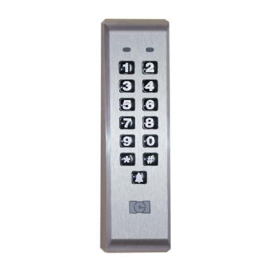
212iLM Mullion (
Features:
v
v
v
v
v
v
v
v
v
Installation:
q
q
q
q
q
q
ILLUMINATED WEATHER RESISTANT
Stand Alone Keypad-Installation Manual
120 User Capability
Illuminated Hardened Keys
Programmable 00-99 Second Relay Activation Time
Remote Trigger Input (REX)
Bell output (timed or continuous)
Designed for Heavy Traffic Application (greater than 1 million cycles)
Surface Mount
Indoor / outdoor Applications
Fully encapsulated
Section 1: Unpacking and checking the packing list
Section 2: Mounting the 212iLM Mullion
Section 3: Wiring the 212iLM Mullion
Section 4: Power Up and System Defaults
Section 5: Programming the 212iLM Mullion
Section 6: Trouble Shooting
Page 1 of 17
) Keypad
6051344
Rev. 1.0
Advertisement
Table of Contents

Subscribe to Our Youtube Channel
Related Manuals for International Electronics 212iLM Mullion

Summary of Contents for International Electronics 212iLM Mullion
- Page 1 Indoor / outdoor Applications Fully encapsulated Installation: Section 1: Unpacking and checking the packing list Section 2: Mounting the 212iLM Mullion Section 3: Wiring the 212iLM Mullion Section 4: Power Up and System Defaults Section 5: Programming the 212iLM Mullion...
-
Page 2: Section 1: Unpacking And Checking The Packing List
Select the appropriate location for the 212iLM Mullion. Mounting height is the same for an electrical switch, 48" on center. The 212iLM Mullion should be Surface Mounted with a 1/4” hole for the wires centered approximately 5/8 of an inch underneath the center of bottom mounting hole (refer to the included mounting template). - Page 3 Situation 1: If you are using a common power supply with the 212iLM Mullion and the Magnetic Lock, (that is to say if you have only one power supply for both the 212iLM Mullion and the lock device), you need to run...
- Page 4 Situation 1: If you are using a common power supply with the 212iLM Mullion and the Electric Strike, (that is to say if you have only one power supply for both the 212iLM Mullion and the lock device), you need to run...
- Page 5 Situation 2: If you are using a separate power supply with the 212iLM Mullion and the Electric Strike, you need to run voltage from the positive of the power supply to the Brown (normally open) wire on the 8 conductor wire harness of the 212iLM.
- Page 6 Step 1: Connect the White with Black trace wire on the 212iLM Mullion harness to the common connection on the REX device. Step 2: Splice a wire to the Black (negative) wire on the 212iLM Mullion harness and connect to the Normally Open connection on the REX device.
-
Page 7: Section 4: Power Up
Step 3: Plug in the power supply. Upon power up, the 212iLM Mullion will cycle through the LED's from left to right twice to indicate proper keypad operation. (If the LED's continue to flash, refer to the trouble shooting section of this manual on page 14). -
Page 8: Section 5: Programming The 212Ilm Mullion
The 212iLM Mullion supports 120 user codes that will energize the main relay. A user code is stored in the memory of the 212iLM Mullion with an individual user location, and may be 1 to 6 digits in length. Each user code has a corresponding user location. To help with the understanding of user locations, think of them like shelves. - Page 9 Step 3: Adding or Changing User Codes. User codes may be 1 to 6 digits in length. The 212iLM Mullion has to be in programming mode to add or change users Enter Programming Mode: 99# (Master code) Next enter the user location. (2, 3, 4, etc.) followed by the # key.
- Page 10 Step 5: Changing the 212iLM Mullion Feedback Options. The 212iLM Mullion has two keypress feedback options that you may choose from. One is an audio feed back. This will activate the on board sounder every time that a key is pressed. The other is a visual feedback.
- Page 11 Step 7: Doorbell Option: When the doorbell feature is enabled there will be visual and audio keypress feedback for the bell button but when the feature is disabled there will be no keypress feedback. This doorbell feature has two modes of operation: timed and continuous.
- Page 12 If the Master code is not working or has been forgotten: Power down the 212iLM Mullion and connect the White with Black trace wire to the Red wire and power up the 212iLM Mullion. This will put the 212iLM Mullion into program mode indicated by the flashing yellow LED.
- Page 13 Programming Options Chart If the pre-programmed default values must be changed or additional functions are desired, the following options may be programmed. • Enter programming mode Press: 99 # (master code)* The master default code is 1234 and the 212iLM must be in programming to make any changes. •...
-
Page 14: Section 6: Trouble Shooting
Section 6: Trouble Shooting. Refer to this section if the 212iLM Mullion is not responding correctly to the operation outlined in this instruction manual. The 212iLM Mullion has been designed to operate with 12-24 Volts AC or DC. Verify that the voltage powering this keypad is within these parameters. - Page 15 International Electronics Incorporated (IEI) warrants its products to be free from defects in material and workmanship, when they have been installed in accordance with the manufacturer’s instructions, and have not been modified or tampered with. IEI does not assume any responsibility for damage or injury to person or property due to improper care, storage handling, abuse, misuse, normal wear and tear, or an act of God.
- Page 16 NOTES: IEI suggests that you make a record of your installation for future reference. Page 16 of 17 6051344 Rev. 1.0...
- Page 17 1 7/16” Diameter of the mounting holes is: 11/64 Diameter of the wiring holes is: This product is designed as a surface 6 1/4” mountable product. The access hole for the wires is determined by the amount of wires that will run through the mounting surface. 3 3/8”...
Need help?
Do you have a question about the 212iLM Mullion and is the answer not in the manual?
Questions and answers