
Related Manuals for Honeywell Notifier VGS-EXP


Summary of Contents for Honeywell Notifier VGS-EXP
- Page 1 VGS-EXP Manuale Utente Rivelatori di gas 4-20mA VGS Infiammabili Manuale utente – User manual Pag. 1 VGS-EXP_manu Doc. M-896.1-VGS-EXP-ITA-ENG Rev A.5 NOTIFIER ITALIA...
-
Page 2: Indice / Index
INDICE / INDEX PRECAUZIONI / Precautions INTRODUZIONE / Introduction CARATTERISTICHE TECNICHE / Technical specifications DISPOSIZIONE DEL SITO D’INSTALLAZIONE / Installation site prearrangement INSTALLAZIONE / Installation Modalità per il corretto montaggio / Correct positioniing mode Schema topografico del circuito /detector circuit layout Configurazione del rivelatore / Detector configuration Collegamento con uscita 4-20mA / 4-20mA output connection Programmazione dei jumpers soglie di allarme / Jumpers programming for alarm thresolds... - Page 3 NOTA BENE: Non cercate di installare la centrale e i dispositivi collegati senza aver letto il presente manuale. PRECAUZIONI Queste istruzioni contengono procedure da seguire per evitare danni ai dispositivi. Si assume che l’utente di questo manuale abbia effettuato un corso di formazione e che sia a conoscenza delle normative vigenti applicabili.
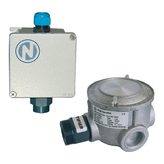
- Page 4 INTRODUZIONE INTRODUCTION Descrizione Description I rivelatori di gas della serie VGS vengono impiegati per VGS gas detectors are used to detect the presence rilevare la presenza di sostanze combustibili, (%LIE) combustible gases (%LEL) Lower Explosion Limit in Limite Inferiore di Esplosività in una atmosfera costituita environments where the principal constituent is air.
-
Page 5: Caratteristiche Tecniche
Caratteristiche tecniche Technical specifications Elemento sensibile Pellistore NEMOTO NET-PEL Sensing element NET-PEL NEMOTO pellistor Corpo sensore Certificato ATEX Sensor head ATEX certificates (eccetto versione Gruppo I) CESI 01ATEX013U o (except Group I version) CESI 01ATEX013U or CESI 01ATEX066U CESI 01ATEX066U Campo di misura 0-100%LEL Measurement range... - Page 6 PREDISPOSIZIONE DEL SITO INSTALLATION SITE D’INSTALLAZIONE PREARRANGEMENT Durante le operazioni di montaggio e installazione, gli At the mounting and installation phase be sure all safety impianti devono essere messi in sicurezza. Ricordiamo precautions have been considered. anche come in fase di installazione sia opportuno tenere Always consider how important it is the correct positioning in considerazione alcune norme generali in quanto un of gas detectors to get the optimum response.
-
Page 7: Installazione
INSTALLAZIONE INSTALLATION Modalità per il corretto montaggio Correct positioning mode Il rivelatore deve sempre essere installato con l’elemento The gas detector is always to be mounted with the sensibile (testa di rivelazione) rivolta verso il basso. Il sensing element placed downward. contenitore del rivelatore, per nessuna ragione deve For no reasons at all the enclosure can be drilled. - Page 8 Collegamento con uscita 4-20mA 4-20mA output connection Il rilevatore viene configurato per avere di default una The default configuration provides a 4-20mA proportional uscita proporzionale 4-20mA. output Per il collegamento del rivelatore con la centrale e Wiring between the detector and the control panel should alimentazione si raccomanda l'uso di cavo schermato.
- Page 9 PROGRAMMAZIONE JUMPERS PER SOGLIE DI ALLARME JUMPERS PROGRAMMING FOR ALARM THRESHOLDS Configurando diversamente i dip-switch presenti sulla modifying dipswitch configuration scheda base si possono modificare le soglie di allarme. motherboard, different alarm thresholds might Anche disponendo della scheda opzionale a 3 relè è obtained.
- Page 10 COLLAUDO E USO TESTING AND USE Accensione Power ON Al momento in cui il rivelatore viene alimentato, si When the detector is powered on, the red LED on the accende, ad intermittenza lenta il LED rosso sulla scheda motherboard starts blinking at slow intermittence. Output base.
-
Page 11: Manutenzione
MANUTENZIONE MAINTENANCE Manutenzione preventiva Preventive maintenance routines Tutti i rivelatori di gas ad uso industriale, sia per gas According to the EN 60079–17, all gas detectors for infiammabili che per gas tossici, devono essere controllati industrial application, either for flammable or toxic gases, ogni tre-sei mesi, secondo la guida CEI 31-35 CAP. - Page 12 VITA DEL RILEVATORE LIFE OF THE DETECTOR RIVELATORI PER SOSTANZE ESPLOSIVE - Durata DETECTORS FOR EXPLOSIVE SUBSTANCES - media 2-4 anni, a seconda dell’ambiente di lavoro. Nel Average life 2-4 year, depending on the working caso di aree “sporche”, quindi con presenza environment.
- Page 13 Via Grandi, 22 E-mail: notifier@notifier.it A Honeywell company Numero Assistenza Tecnica: 039-9301410 Every care has been taken in the preparation of this data sheet but no liability can be accepted for the use of the information therein. Design features may be changed or amended without prior notice.
Need help?
Do you have a question about the Notifier VGS-EXP and is the answer not in the manual?
Questions and answers