
Related Manuals for Manson Engineering Industrial KPS-6000 Series


Summary of Contents for Manson Engineering Industrial KPS-6000 Series
- Page 1 KPS-6000 series REMOTE PROGRAMMABLE POWER SUPPLY WITH ETHERNET NETWORK CONNECTIVITY DC WAVE FORM GENERATOR 3 SELECTABLE VOLTAGE & CURRENT RANGES USER MANUAL REV.2 2022-03 7673-6600-0001...
-
Page 2: Table Of Contents
Table of Contents PRECAUTIONS Warning: Caution: Copy Right Operation Environmental Condition: ACCESSORIES INTRODUCTION SPECIFICATIONS 5 - 9 INDICATORS and CONTROLS 10 - 11 Back Panel OPERATION PROCEDURES Adjusting Output Voltage and Current Upper Voltage and Current Limit Adjustment Select and Adjust 3 Preset Value of Voltage and Current Output ON/OFF (Include Power up ON/OFF Setting) Lock/Unlock of Front Panel Watt-meter and Amp-meter Selection... -
Page 3: Precautions
All rights reserved. No part of this publication may be reproduced, or transmitted in any form or by any means without the written permission from Manson Engineering Industrial Ltd. Changes in the manual. Manson Engineering Industrial Ltd. has the right to update and change the content of this manual without any notice and obligation. -
Page 4: Operation Environmental Condition
Operation Environmental Condition: 10-80% R.H. Altitude up to 2000m Installation category: CAT 2 Pollution degree: 2 Mains supply voltage fluctuation up to ±10% of the specified operating voltage. ACCESSORIES AC Power cord CDROM include user manual, USB driver and PC control software Output cable with right angle safety plug and crocodile clip USB cable INTRODUCTION... -
Page 5: Specifications
SPECIFICATIONS Models KPS-6100 KPS-6102 KPS-6104 OUTPUT Variable Output Voltage 1 - 18VDC 1 - 36VDC 1 - 60VDC Variable Output Current 0 - 10A 0 - 5A 0 - 2.5A VOLTAGE REGULATION Load (10-90% Rated Current) ≤50mV Line (180-264VAC Variation) ≤20mV CURRENT REGULATION ≤100mA... - Page 6 Models KPS-6200 KPS-6202 KPS-6204 OUTPUT Variable Output Voltage 1 - 18VDC 1 - 36VDC 1 - 60VDC Variable Output Current 0 - 20A 0 - 10A 0 - 5A VOLTAGE REGULATION ≤50mV Load (10-90% Rated Current) Line (180-264VAC Variation) ≤20mV CURRENT REGULATION Load (10-90% Rated Voltage) ≤100mA...
- Page 7 Models KPS-6300 KPS-6302 KPS-6304 OUTPUT Variable Output Voltage 1 - 16VDC 1 - 32VDC 1 - 60VDC Variable Output Current 0 - 30A 0 - 15A 0 - 8A VOLTAGE REGULATION ≤50mV Load (10-90% Rated Current) Line (180-264VAC Variation) ≤20mV CURRENT REGULATION Load (10-90% Rated Voltage) ≤150mA...
- Page 8 Models KPS-6400 KPS-6402 KPS-6404 OUTPUT Variable Output Voltage 1 - 16VDC 1 - 32VDC 1 - 60VDC Variable Output Current 0 - 40A 0 - 20A 0 - 10A VOLTAGE REGULATION ≤50mV Load (10-90% Rated Current) Line (180-264VAC Variation) ≤20mV CURRENT REGULATION Load (10-90% Rated Voltage) ≤150mA...
- Page 9 Models KPS-6600 KPS-6602 KPS-6604 OUTPUT Variable Output Voltage 1 - 16VDC 1 - 32VDC 1 - 60VDC Variable Output Current 0 - 60A 0 - 30A 0 - 15A VOLTAGE REGULATION ≤50mV Load (10-90% Rated Current) Line (180-264VAC Variation) ≤20mV CURRENT REGULATION Load (10-90% Rated Voltage) ≤200mA...
-
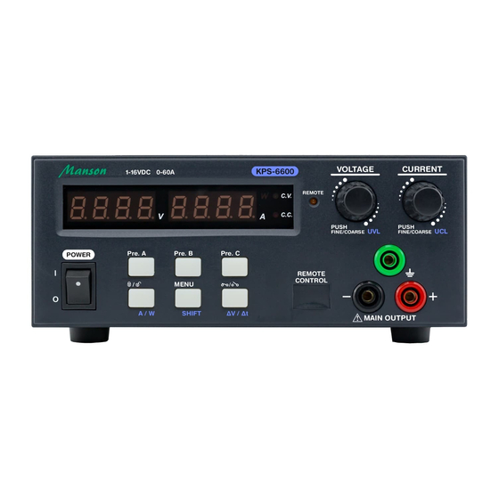
Page 10: Indicators And Controls
INDICATORS and CONTROLS Main Power Switch The main power of power supply. Switch to I position to power on the power supply and switch to O position to power off the power supply. Volt. Meter Amp. Meter Power Indicator Indicate the right part 4 digits LED is watt-meter. The display is showing actual output Power value. - Page 11 Lock & A/W Selection Button Press this button to LOCK and UNLOCK the keypad and knobs. This button ON indicate the keypad and knobs are being locked. When using with SHIFT key on, it is used to select the right hand side display operate as watt-meter or amp-meter. MENU &...
-
Page 12: Back Panel
Back Panel Main Output Terminal (only for 6300, 6400, 6600, 6602) Optional Ethernet Card (Manson model AEN-8102) Cooling Fan AC Input Socket Analogue Remote Control Port (More details please refer to section 8) OPERATION PROCEDURES Adjusting Output Voltage and Current Adjust Output Voltage Rotate Voltage Knob clockwise to INCREASE output voltage. -
Page 13: Upper Voltage And Current Limit Adjustment
Upper Voltage and Current Limit Adjustment Upper Voltage Limit (UVL) The Upper Voltage Limit is feature to let user to set maximum value for voltage adjustment. This feature can help to prevent accidentally adjust to very high output voltage to cause damage on object under testing. During increasing output voltage and hit the UVL, the display will show you alert as follow;... -
Page 14: Select And Adjust 3 Preset Value Of Voltage And Current
Adjust Upper Current Limit: The second function of Current knob is for UCL adjustment. Press and the button will ON. Then press Current knob. The display will show as follow; Rotate Current knob to adjust the value. Press to confirm setting. If the new UCL value is lower than set current, it will show UCL Error alert. -
Page 15: Lock/Unlock Of Front Panel
Steps to change setting; Step 1 Press and hold to enter menu. Step 2 Rotate Volt. knob to select PU menu. The display show Step 3 Press Volt. knob to enter PU setting. The display show Step 4 Rotate Curr. knob to change setting to The output is set to as same as last status. -
Page 16: Ramp Up/Down Generator
Ramp Up/ Ramp Down Generator The KPS series has function to generate waveform with ramp up and ramp down. It allow to set 10 steps of wave. The Ramp Up/Ramp Down function can be done by both Remote Programming via USB interface to your PC and on panel manual programming. - Page 17 Steps to Run ramp up/ ramp down wave; Step 1 Press to switch on output. Step 2 Press and the button will on. Step 3 Press to run dvdt program. Examples: Example 1 Triangular Waveform. Setting Value: Set item Value Explanation Set 2 steps to run.
- Page 18 Example 2 Saw-tooth Waveform. Setting Value: Set item Value Explanation Set 2 steps to run. Step 1 and Step 2 Run 6 cycle only Set Step 1 voltage to 2.5V Set Step 1 current to 5A Set Step 1 run time to 3s (Ramp UP from step 1 voltage to step 2 voltage in 3s) Set Step 2 voltage to 12V Set Step 2 current to 10A...
- Page 19 Example 3 Rectangular Waveform Setting Value: Set item Value Explanation Set 4 steps to run. From Step 1 and Step 4 Run 4 cycle only Set Step 1 voltage to 2.5V Set Step 1 current to 5A Set Step 1 run time to 0s (Edge UP from step 1 voltage to step 2 voltage in 0s) Set Step 2 voltage to 12V Set Step 2 current to 10A...
- Page 20 Example 4 Irregular Waveform Setting Value: Set item Value Explanation Set 7 steps to run. Step 1 and Step 7 Run forever Set Step 1 voltage to 2.5V Set Step 1 current 5A Set Step 1 run time to 3s (Ramp UP from step 1 voltage to step 2 voltage in 3s) Set Step 2 voltage to 12V Set Step 2 current to 10A...
-
Page 21: Factory Reset
Set Step 6 voltage to 7.8V Set Step 6 current to 4A Set Step 6 run time to 5s (Ramp DOWN from step 6 voltage to step 7 voltage in 5s) Set Step 7 voltage to 2.5V Set Step 7 current to 9.9A Set Step 7 run time to 5s (Keep at 2.5V by 5s, since step 7 voltage = step 1 voltage) Factory Reset... -
Page 22: Remote Control Interface Selection
Remote Control Interface Selection The KPS bundles with USB port for remote control. The Ethernet Card is optional accessory. The remote control interface can be selected in menu. Steps for Remote Control interface selection; Step 1 Press and hold button to enter setting menu. Step 2 Rotate VOLT. -
Page 23: 6.11 Voltage And Current Setting Timeout Time
6.11 Voltage and Current setting Timeout time This timeout time is the time that the display auto exit from voltage and current setting and return to normal display. The timeout time can be set from 1s to 30s. Steps for changing timeout time; Step 1 Press and hold button to enter setting menu. -
Page 24: Menu Flow
MENU FLOW P.24... -
Page 25: Analogue Remote Control Mode
ANALOGUE REMOTE CONTROL MODE There are two methods for remote control of current and voltage adjustment. Both methods require both the current and the voltage remote control to be set up together in order to make the remote control functional. The output on-off is optional and will not affect either voltage or current control. - Page 26 To exit from the Analogue remote control mode Press the [Lock/ Unlock] button (10) to exit from the Analogue Remote Control Mode. Take note of the orange [REMOTE] LED is OFF. Method A Using two external variable DC voltage sources. Remote socket pin assignment for external variable voltage source.
- Page 27 Method B Use two 0 – 5K Ohm variable resistors Both variable resistors must be set up in order for the remote control to be functional. CC current setting by remote control. Adjust the CC current setting using the 0-5k Ohm variable resistor.
- Page 28 Output ON/ OFF Remote Control CAUTION ! The allowable fastest output on-off frequency is two cycles per second. The power supply may not work normally when On-Off is over two cycles per second due to triggering of unit’s protection system. By default, Pin 5 is in open circuit and output is on.
Need help?
Do you have a question about the KPS-6000 Series and is the answer not in the manual?
Questions and answers