Table of Contents
Advertisement
Quick Links
Advertisement
Table of Contents

Related Manuals for ComNav Technology M300


Summary of Contents for ComNav Technology M300
- Page 1 M300 GNSS Receiver Quick Tour ComNav Technology Ltd. www.comnavtech.com...
-
Page 2: Table Of Contents
3.4.2Memory management ........................ 11 3.4.3 Rinex convert ..........................11 3.5 Sending command to Receiver ......................12 Chapter 4 M300 Frequently Used ASCII Command ..................14 4.1 Base station configuration ........................ 14 4.2 Rover configuration .......................... 15 4.2.1 Set Rover to differential mode ....................15 4.2.2 Check the solution type ...................... -
Page 3: Chapter1 M300 Package List
Some special application case, special antenna supplied 1.2 M300 enclosure receiver introduction M300 receiver; with 1 GNSS OEM card inside, and integrate with radio data link, which is mainly used in high accuracy positioning, Monitoring, construction, marine and so on. M300 GNSS receiver... -
Page 4: Chapter2 System Installation
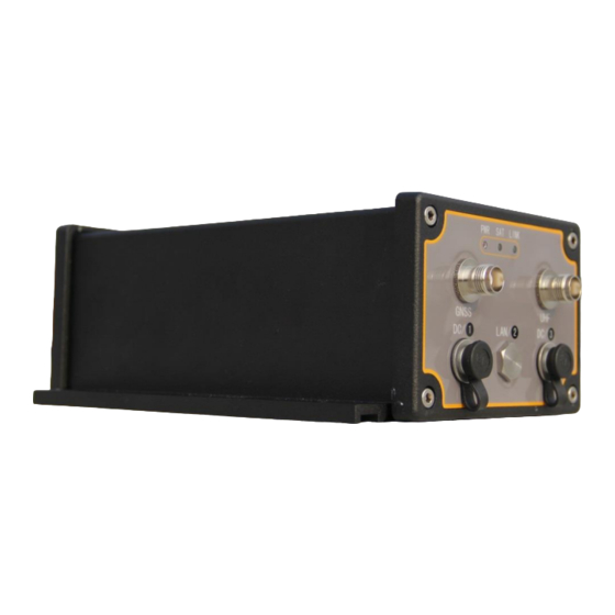
Chapter2 System installation 2.1 Front panel introduction M300 receiver Ref. # Description ❶ 3 LED, indicates the work status of Receiver. a; Power indicator; after power on, this LED will light in red colour b; satellites indicator, it will flash several times every 5 seconds, which means how many satellites locked by receiver. -
Page 5: Chapter 3 Configuration Oem Card By Cru Software
Chapter 3 Configuration OEM Card by CRU software Introduction Compass Receiver Utility is a windows-based GUI that allows you to access your receiver’s many features without the need to use a terminal emulator or to write special software. CRU lets you easily communicate and configure your receiver via serial port, Ethernet connection a PC the Windows XP or Windows 7 operating system. -
Page 6: Receiver Configuration
Ref. # Description ❶Connection status; SN No. of receiver, the data download path. You can select the data download path from the left function bar-> Folders, select the folder path. ❷Main menu; all the operation of software menu can be found here ❸Shortcut bar;... - Page 7 Local log; log the raw data to local PC, the file name will be auto named in the current folder path, in this mode; you can define the raw data message type.
-
Page 8: Get Correction Message From Radio Or Ntrip
3.2.2 Get correction message from Radio or Ntrip . 3.2.2.1Internal Radio setup This step is for setting up internal UHF frequency and protocol,you must use your laptop link with DC/3 port to set radio parameters. Go to , set up the Frequency and protocol (same as external transmit radio). -
Page 9: Work Mode Configuration
Change the work mode (Base station or Rover); edit the command package that sent to OEM card. For example, if you want to start M300 as Base station, go to , some predefined command package list can be seen below;... -
Page 10: Main Information Check
Click apply and follow the indication to start base M300 as Base station. After starting base station, use DC/3 link with external radio, set the external radio interface band rate as 38400 bps (to match with the correction message) 3.3 main information check... -
Page 11: Rtk Status Indication
Make sure your PC is log on internet; this will show the current position on global map. 3.3.2 RTK status indication After receiver receives correction message, the receiver will calculate the ambiguity and turn to differential mode. ❶Position mode; SINGLE->Narrow Float ->NARROW INT (autonomous mode-> RTK Float- >RTK fixed) ❷Differential age;... -
Page 12: Raw Data Management
3.4 Raw data management 3.4.1 Raw data download Raw data can be recorded in the memory of receiver or PC. Download the data from memory of receiver; go to , the files list will appear in the Main window, you can modify the raw data, such as station name and antenna height. After selecting the file and right click, download to the current folder. -
Page 13: 2Memory Management
3.4.2Memory management Go to the Shortcut Bar, go to , you can format the memory or Clear the files that you delete to the recycle bin. 3.4.3 Rinex convert After downloading to the project folder, you can covert the Raw data to Rinex format, Go to the function bar, click , you will see the raw data in current project. -
Page 14: Sending Command To Receiver
3.5 Sending command to Receiver In the shortcut men, go to , in this page you can send ASIC command to receiver. - Page 15 Operation tips; Interfacemodecom3 autoauto on Set com 3 auto detecting correction message and get to differential mode, but at the same time any command sent through com3 will not respond. Interfacemode com3 compass compass on Set com 3 not to detect correction message and receiver will turn differential mode to autonomous mode, and then COM3 can accept all the OEM card commands.
-
Page 16: Chapter 4 M300 Frequently Used Ascii Command
Chapter 4 M300 Frequently Used ASCII Command Tips; 1. All the commands send to receiver, do not distinguish between letter case; Such as; Log version=LOG VERSION. 2. After inputting every command, press Enter button to change line and input another command. -
Page 17: Rover Configuration
com com3 9600 saveconfig Tips; if you want to start the base station on known points, such as (31.123 N degree, 123.456E, 45 Height), please fix the base station coordinates by using the command Fix Position 31.123 121.456 45. 4.2 Rover configuration 4.2.1 Set Rover to differential mode INTERFACEMODE <port><input-message><output-message>... -
Page 18: Check The Solution Type
Command Description Com com3 9600 Match the correction message band rate with Base station interfacemode com3 auto auto on Auto detect the correction message type Saveconfig Save the setting to the receiver 4.2.2 Check the solution type Send command to output GPGGA information to check the solution type; Log <port>... -
Page 19: Satellites Constellation System Configuration
Change the band rate command Com <port><band rate> For example; com com1 9600 /change com1 band rate as 9600bps/ 4.4 satellites constellation system configuration Command Description lockout bd2 Lock out Beidou system lockout gps Lock out GPS system Lockout glonass Lock out glonass system Unlockoutall Unlock all GNSS system... -
Page 20: Update The Oem Card
SET CPUFREQ 624 \change CPU frequency more faster to support 20HZ\ Morally we use 10HZ, 5HZ, 2HZ and 1HZ, the relative command is 0.1/0.2/0.5/1 After sending those commands, the raw data will output by receiver and save the data in your PC. -
Page 21: Update Radio Firmware
4.7 update radio firmware The update process is as same as updating OEM board. Download the radio firmware from ComNav website, use the data cable link with DC3 of M300 to update (update OEM firmware use DC1). Open the update file***.exe, go to App->Link Setup, select the right serial port of your PC, then click ok, click link. - Page 22 Click update, the programme bar will make progress, this will take 1-3 seconds.
- Page 23 Appendix A 7 Pin definition of M300. 7 pin Lemo Description Signal GND TX data out (TXD) NONE NONE Power In (+) Serial data in (RXD) Last review by Simon 2014.01.14 Any feedback please send email to Support@comnavtech.com...
Need help?
Do you have a question about the M300 and is the answer not in the manual?
Questions and answers