Advertisement
Available languages
Available languages
Quick Links
INDEX/ÍNDICE
(EN)
MOUNTING INSTRUCTIONS DPS KIT
J4C 20 TO 85
(ES)
INSTRUCCIONES MONTAJE KIT DPS
J4C 20 A 85
(EN)
MOUNTING INSTRUCTIONS DPS KIT
J4C 140 TO 300
(ES)
INSTRUCCIONES MONTAJE KIT DPS
J4C 140 A 300
.....................................................................................................................................................................
.....................................................................................................................................................................
............................................................................................................................................................
............................................................................................................................................................
2
5
8
11
Advertisement

Related Manuals for J4C DPS KIT 20/85

Summary of Contents for J4C DPS KIT 20/85
- Page 1 INDEX/ÍNDICE (EN) MOUNTING INSTRUCTIONS DPS KIT J4C 20 TO 85 ..................................(ES) INSTRUCCIONES MONTAJE KIT DPS J4C 20 A 85 ..................................(EN) MOUNTING INSTRUCTIONS DPS KIT J4C 140 TO 300 ................................(ES) INSTRUCCIONES MONTAJE KIT DPS J4C 140 A 300...
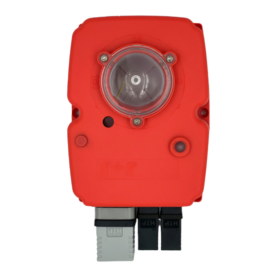
- Page 2 (EN) ASSEMBLY INSTRUCTIONS DPS KIT J4C 20 TO 85 The DPS is a device for the J4C electric actuator that turns the actuator into a servo controlled valve positioner. The DPS is a modulus with a microprocessor (CPU) which digitally manages the analogical input and output and compare them with the position of the actuator to establish a uniform relation.
-
Page 3: Kit Components
* Fill in the document inside the kit, and send it to the fax number (93 871 32 72) or e-mail: info@jjbcn.com, shown in the document. PREPARING THE COVER: The cover of the kit is for a J4C BLUE-20, 35 and 55 models. In case you want to mount a kit on a J4C85, follow the instructions:... - Page 4 Carefully remove the position indicator. Remove the cables (from the cover) connected to the Remove the screw, which is fixing Remove the 6 screws, which are fixing Carefully lift the cover. actuator PCB (Fig. A, B and C). the hand wheel. the body to the cover of the actuator Place the mentioned cables as per (Fig.
- Page 5 INSTRUCCIONES DE MONTAJE DPS KIT J4C 20 A 85 El DPS es un accesorio para los actuadores eléctricos J4C que los convierte en posicionador de válvulas servo controladas. El DPS es un módulo que incorpora un micro- procesador (CPU) el cual controla digitalmente la entrada y la salida de señal analógica y compara...
-
Page 6: Componentes Del Kit
* Rellenar el documento adjunto al KIT y enviarlo al número de fax (93 871 32 72) o por e-mail: info@jjbcn.com PREPARACIÓN DE LA TAPA: La tapa del kit, viene montada para poder tapar J4C-20, 35 y 55. En caso de necesitar una tapa para un J4C85, seguir las siguientes instrucciones:... - Page 7 Retirar cuidadosamente el indicador visual de posición. Desconectar el cableado de la tapa que está conectado Desatornillar el tornillo que fija el Desatornillar los 6 tornillos de unión Retirar cuidadosamente la tapa. a la electrónica. (Fig. A, B y C). volante y retirarlo.
- Page 8 (EN) ASSEMBLY INSTRUCTIONS DPS KIT J4C 140 TO 300 The DPS is a device for the J4C electric actuator that turns the actuator into a servo controlled valve positioner. The DPS is a modulus with a microprocessor (CPU) which digitally manages the analogical input and output and compare them with the position of the actuator to establish a uniform relation.
- Page 9 VERY IMPORTANT!!!! PLEASE FOLLOW THE INSTRUCTIONS STEP BY STEP. BEFORE CONNECTING “A” PLUG TO THE ACTUATOR, CHECK THAT THE VOLTAGE IS THE SAME AS THE ONE SPECIFIED ON THE LABEL (CARTER). TO CONVERT A STANDARD (ON-OFF) J4C ELECTRIC ACTUATOR INTO A MODULATING FUNCTION WITH POSITIONER, PROCEED AS FOLLOWS:...
- Page 10 Remove the screw, which is fixing Remove the 8 screws, which are fixing Remove the cables (from the cover) connected to the actuator PCB (Fig. A, B and C). Carefully lift the cover. the hand wheel. the body to the cover of the actuator. Carefully remove the position indicator.
- Page 11 INSTRUCCIONES DE MONTAJE DPS KIT J4C 140 A 300 El DPS es un accesorio para los actuadores eléctricos J4C que los convierte en posicionador de válvulas servo controladas. El DPS es un módulo que incorpora un micropro- cesador (CPU) el cual controla digitalmente la entrada y salida de señal analógica y compara...
- Page 12 MUY IMPORTANTE!!!! ANTES DE CONECTAR EL ACTUADOR A LA CORRIENTE, REVISAR QUE EL VOLTAJE COINCIDA CON EL DE LA ETIQUETA PEGADA AL ACTUADOR. PARA CONVERTIR UN ACTUADOR ELECTRICO STANDARD J4C (ON-OFF) EN UN ACTUADOR CON POSICIO- NADOR, PROCEDER DE LA SIGUIENTE MANERA:...
- Page 13 Desatornillar el tornillo que fija el Desatornillar los 8 tornillos de unión Desconectar el cableado de la tapa que está conectado a la electrónica. (Fig. 5A, 5B y 5C). Retirar cuidadosamente la tapa. volante y retirarlo. entre la tapa y el cuerpo. Retirar cuidadosamente el indicador visual de posición.
Need help?
Do you have a question about the DPS KIT 20/85 and is the answer not in the manual?
Questions and answers