
Subscribe to Our Youtube Channel
Related Manuals for iTechworld 1000W


Summary of Contents for iTechworld 1000W
- Page 1 Pure Sine Wave Inverters 12 Volt Inverters (1000W/2000W/3000W Models) USER GUIDE (Revised 01/2022)
-
Page 2: Warnings And Safety
Important: Please read and understand the entirety of this user guide before using your iTechworld inverter. Any misuse may result in damage to the unit and/or cause harm or serious injury to the user. !!FAILURE TO FOLLOW THESE INSTRUCTIONS MAY RESULT IN... - Page 3 DANGER ELECTRICAL SHOCK HAZARD: Operating the inverter without proper grounding may result in death or serious injury. Please ensure that proper ground connections are made during installation. Please consult a licensed electrician if you are unsure. DANGER ELECTRICAL SHOCK HAZARD: Before attempting to clean the inverter disconnect DC power and any circuits connected to the inverter.
- Page 4 Warning: Batteries can supply very large currents in the event of a short circuit. A fuse must be installed on the positive supply cable as close as practical to the battery. Failure to do so provides inadequate protection in the event of a short circuit and may result in a fire hazard.
- Page 5 USER GUIDE Introduction: Thank you for purchasing the iTechworld pure sine wave inverter. These inverters produce a pure sine wave output, matching the output of your home 240V AC power point, allowing you to power sensitive electronic appliances, such as laptops and many AC powered devices anywhere.
- Page 6 Fuse Size 175A 250A 450A High Voltage 16VDC ± 0.5VDC Protection Low Voltage 10.5VDC ± 0.5VDC Protection Efficiency More than 90% Output Rated 1000W 2000W 3000W Output Power Surge Power 1200W~ 2400W~3000W 3600W~4500W (10 sec) 1500W Surge Power 1500w~ 3000W~4000W...
-
Page 7: Front Panel
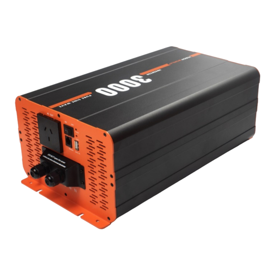
Front Panel Figure 1- 1000W/2000W inverter front panel AC Output Receptacle Main Switch Power LED Indicator Fault LED Indicator 5V USB Socket Remote Control Port (RJ11) For connecting the optional remote- control switch panel. Chassis Ground Terminal... - Page 8 Front Panel Continued Figure 2- 3000W inverter front panel AC Output Receptacle Main Switch Power LED Indicator Fault LED Indicator 5V USB Socket Remote Control Port (RJ11) For connecting the optional remote- control switch panel. Chassis Ground Terminal Hard-wire terminal block for use if loads are 15A or more (MUST BE CONNECTED BY A LICENSED ELECTRICIAN)
- Page 9 Front Panel Continued A. AC Output Receptacle Figure 3- Standard 10A 240VAC Australia / New Zealand receptacle For connecting 240VAC appliances to the inverter B. Main Switch The main switch is used for turning ON or OFF the output of the inverter.
- Page 10 Front Panel Continued G. Chassis Ground Terminal A proper ground connection must be made before using the inverter. The inverter is grounded through the grounding terminal located on the front panel near the 240V outputs. The chassis ground terminal must be connected to the negative terminal of the DC input.
-
Page 11: Rear Panel
Rear Panel Figure 5- 1000W/2000W inverter rear panel Figure 6- 3000W inverter panel Cooling fan DC Input Terminals A. Cooling fan The cooling fan(s) on the inverter are temperature and/or load controlled. The fan(s) will automatically turn on when the AC load is 20% or... - Page 12 Please keep the DC input cables as short as possible, if longer run cables are required, please use a larger cable. Recommended Cable Size and Fuse Rating. Model Cable Size Fuse/ Circuit Breaker 1000W 10mm² for 175A Inverter lengths <1M 2000W 25mm²...
-
Page 13: Remote Control
Remote Control (Sold Separately) Figure 7 - Optional Remote Control A Remote Control Main Switch B Fault LED Indicator AC Output Indicator D Inverter Load Indicator DC Input Power Indicator Battery Capacity Indicator A. Remote Control Main Switch The main switch is used for turning ON or OFF the output of the inverter. - Page 14 C. AC Output Indicator Will illuminate green to show that the inverter is outputting 240VAC power. D. Inverter Load Indicator Displays the approximate load being drawn from the inverter. E. DC Power Indicator Will illuminate green to show that DC power is being supplied to the inverter.
-
Page 15: Installation
INSTALLATION Mounting the inverter The location where the inverter is to be mounted must be: • Dry: Do not allow any liquids to drip or splash onto the unit. • Cool: Do not install in direct sunlight or close to any heat sources, the ideal ambient air temperature is between 15°C to 25°C. - Page 16 Note: This inverter may generate radio frequency energy, if not installed and used in accordance with the instructions in this user guide, this inverter may cause interference with radio communications. There is no guarantee that interference will not occur in a particular installation. If the inverter does cause interference to radios or television reception, which can be determined by turning the inverter off and on, if this is the case you may try to correct the interference by one or more of the...
- Page 17 INSTALLATION CONTINUED DANGER ELECTRICAL SHOCK HAZARD: iTechworld recommends that all wiring and installation be done by a certified technician or licensed electrician to ensure all applicable electrical wiring regulations and installations codes are met. Failure to follow these instructions may result in damage to the unit and could also result in may result in death or serious injury.
- Page 18 Figure 8 – recommended wiring diagram.
-
Page 19: Connecting The Inverter
Connecting the inverter Before connecting the DC input connections to the inverter, make sure that the main and remote main switch (if remote is installed) (refer to Figures 1, 2 and 7) are in the OFF position. 1. Connect one end of the positive DC input cable to the inverter’s positive DC input terminal. -
Page 20: Operating The Inverter
Operating the inverter 1. Before turning on the inverter, make sure the connected AC appliance is turned OFF. 2. Turn on the inverter by moving the Main Switch to the ON position. 3. Once the Power LED indicator is illuminated, turn on the connected AC appliance. -
Page 21: Troubleshooting
The polarity of the DC The inverter will need to input been be returned to reversed and blown iTechworld for further the internal fuses. assessment. (NOTE: This may have caused permanent damage inverter, and void all... - Page 22 240V socket 4. Turn on the AC appliance 5. If there is still no output, contact iTechworld inverter Low DC input voltage 1. Check that beeps twice warning. battery is not flat, The voltage at the DC...
- Page 23 Use thicker cable if required. 3. Check for any loose connections on the DC input circuit. Troubleshooting Continued Symptom Possible Cause Solutions The inverter beeps 4 Overvoltage 1. Check that times and the red detected on the DC voltage at the DC Fault Indicator LED input.
- Page 24 20% load internal temperatures are at 45°C). If the cooling fans functioning, inverter will need further assessment, please contact iTechworld. 2. If functioning, check that all ventilation slots openings are not obstructed. Also ensure that adequate cool air is...
- Page 25 Indicator exceeded the surge illuminates, rating there inverter) output.
-
Page 26: Maintenance And Warranty
12 months from the date of purchase. This warranty will be considered void if the unit has been misused, altered, or accidentally damaged. iTechworld will not be liable for any amount of damage in excess of the retail purchase price of the unit under any circumstances. - Page 27 If such a unit is returned within the warranty period, iTechworld will repair the unit or, at its discretion, replace it, free of charge. If the unit is repaired, new or reconditioned replacement parts may be used, at the manufacturer’s discretion.
- Page 28 Contact iTechworld 281 Great Eastern Hwy Burswood WA 6100 Phone: 1300 483 249 Website: www.itechworld.com.au E-mail: service@itechworld.com.au...
Need help?
Do you have a question about the 1000W and is the answer not in the manual?
Questions and answers