Table of Contents
Advertisement
Quick Links
Installation and Operation Manual
Compact RDMS
All Quasonix receiver products are under U.S. Department of Commerce jurisdiction categorized as
No part of the document may be circulated, quoted, or reproduced for distribution without prior written approval from
3
rd
Generation Dual Channel
TM
Telemetry Receiver-Combiner
Quasonix, Inc.
6025 Schumacher Park Dr.
West Chester, OH 45069
01 May 2022
Revision 1.0
Applies to RDMS™ System Version 19.3
Specifications subject to change without notice.
5A991; not covered by ITAR
Quasonix, Inc.
Copyright Quasonix, Inc., All Rights Reserved.
ISO 9001:2015
Certified
Advertisement
Table of Contents

Related Manuals for Quasonix Compact RDMS Telemetry Receiver-Combiner

Summary of Contents for Quasonix Compact RDMS Telemetry Receiver-Combiner
- Page 1 Applies to RDMS™ System Version 19.3 Specifications subject to change without notice. All Quasonix receiver products are under U.S. Department of Commerce jurisdiction categorized as 5A991; not covered by ITAR No part of the document may be circulated, quoted, or reproduced for distribution without prior written approval from Quasonix, Inc.
-
Page 2: Table Of Contents
Electrical Signals ........................15 Operating Instructions .......................... 17 Power-on Operation ........................17 Reset IP Address to Default ...................... 17 Browser Interface ..........................19 Network Screen ......................... 19 Monitor Screen .......................... 21 5.2.1 Signal Graph and Signal Indicators ..................24 Quasonix, Inc. - Page 3 AFC Mode – Off ....................... 45 5.4.3.5.3 5.4.3.6 Best Channel Selector ...................... 45 5.4.3.7 Time Aligner ........................47 5.4.4 PCM Encoding........................48 5.4.5 Channel A Video Output ......................49 5.4.6 Channel B Video Output ......................50 5.4.7 Channel A Video Scale ......................50 Quasonix, Inc.
- Page 4 AGC Time Constant ...................... 67 5.4.13.6 AGC Freeze ........................67 5.4.13.7 AGC Zero Mode ......................68 5.4.13.8 AGC Compensate ......................68 5.4.13.9 AM Bandwidth ....................... 68 5.4.13.10 AM Polarity ........................68 5.4.13.11 AM Scale ........................69 5.4.13.12 Downconvert Antenna ....................69 Quasonix, Inc.
- Page 5 Monitor Page Default Update Rate ..................98 Footer Tool Bar .......................... 98 5.7.1 Help ............................98 5.7.2 Page Access .......................... 99 5.7.3 Export ..........................100 5.7.4 Import ..........................101 Performance Specifications ....................... 103 Power ............................103 RF Frequency Error ......................... 103 Quasonix, Inc.
- Page 6 Appendix C - PCM Framer/Deframer Function ................123 13.1 PCM Framer ..........................123 13.2 PCM Deframer ......................... 124 Appendix D – Factory Reset Values ....................125 Appendix E – Import Quasonix Root Authority Certificate ............. 130 15.1 Firefox ............................130 Quasonix, Inc.
- Page 7 Figure 26: Best Channel Indicator-Ch 1 ...................... 30 Figure 27: Best Channel Indicator-Ch 2 ...................... 30 Figure 28: Best Channel Data Quality Better than Combiner Data Quality ..........30 Figure 29: Best Channel Indicator Off (Grey) ..................... 31 Figure 30: Monitor Display Menu ........................ 31 Quasonix, Inc.
- Page 8 Figure 64: Forward Error Correction Window, LDPC Mode Drop Down Menu .......... 53 Figure 65: Forward Error Correction Window ..................... 54 Figure 66: I and Q Data Streams Independently Encoded ................. 55 Figure 67: I and Q Data from Single Convolutional Encoder ..............55 Quasonix, Inc.
- Page 9 Figure 101: Data Generator, Test Data Drop Down Menu ................. 73 Figure 102: Data Generator, Data Rate Selection ..................74 Figure 103: Data Generator, Pattern Selection................... 74 Figure 104: Data Generator, Inversion Drop Down Menu ................74 viii Quasonix, Inc.
- Page 10 Figure 137: System Information Screen, Additional Information ..............90 Figure 138: Browser Interface, About ......................91 Figure 139: About, System Version, Firmware Update Link ............... 91 Figure 140: Firmware Update, Procedure and Notes ................. 92 Figure 141: Firmware Update, Upload Status ..................... 93 Quasonix, Inc.
- Page 11 Figure 172: Firefox Downloading Certificate Window ................131 Figure 173: Firefox Certificate Viewer-Quasonix Root CA ............... 132 Figure 174: Firefox Certificate Manager with Quasonix Root CA Added ..........133 Figure 175: Internet Properties, Content Tab ................... 134 Figure 176: Certificates Screen ........................ 135 Figure 177: Windows Certificate Import Wizard..................
- Page 12 Telemetry Receiver-Combiner Figure 178: Windows Certificate Import Wizard-Browse ................136 Figure 179: Windows Certificate Import Wizard-Choose Certificate Store ..........137 Figure 180: Certificates, Quasonix Certificate Imported ................138 List of Tables Table 1: Model Configuration Example ......................2 Table 2: Band Configuration Codes ......................5 Table 3: Connector Descriptions .........................
-
Page 13: Introduction
1.1 Description Generation Compact RDMS™ Telemetry This document describes the installation and operation of the Quasonix 3 Receiver-Combiner and is updated to match RDMS™ System Version 19.3. The RDMS™ (Receiver / DeModulator / bit Synchronizer) is designed to downconvert, demodulate, and bit synch to a variety of RF telemetry signals from flight-test aircraft. -
Page 14: Nomenclature
*SOQPSK-STC 0: No Figure 1: Compact RDMS™ Telemetry Receiver-Combiner Part Number Construction Specifications are subject to change. Contact Quasonix for questions regarding your specific receiver. 1.2.1 Options The available options are listed below. Refer to section 1.2.2 for detailed descriptions of each option. Please contact Quasonix for assistance ordering receiver options. -
Page 15: Detailed Option Descriptions
1.2.2.3 Adaptive Equalizer - EQ The Adaptive Equalizer option in the Quasonix receiver improves reception in multipath channels by using digital signal processing to compensate for the signal distortion due to multipath. This option is compatible with standard telemetry applications and installations and it works with any brand of transmitter. - Page 16 The Viterbi Decoder control requires the K7 option, and the RDMS must be set to one of the following PSK modes: BPSK, QPSK, AQPSK, AUQPSK, OQPSK, or UQPSK. Viterbi decoding and Reed-Solomon decoding can be used together or separately. Quasonix, Inc.
-
Page 17: Band Configurations
1750.0 1850.0 2200.0 Base 2394.5 4400.0 Base 5150.0 400.0 Base Base Base Lower L Upper L Freq. Code Legend: Frequency Gap Standard (Base) Frequency Range Extended Frequency Range (available by selecting Extended Tuning = 1 in part number) Quasonix, Inc. -
Page 18: Additional Band Codes
The contents of the box include the following: • Compact RDMS™ Telemetry Receiver-Combiner • 50 ohm terminators, preinstalled on IF output • MDM-25, IP Reset Default connector A copy of the Installation and Operation manual is included with the Browser Interface software (Help option). Quasonix, Inc. -
Page 19: Specifications
250 kHz, 500 kHz, 1 MHz, 2 MHz, 4.5 MHz, 10 MHz, 20 MHz, 40 MHz. Automatic selection based on modulation type and data rate, with manual override IF bandwidths Optional: 70 kHz, 1.4 MHz, 3 MHz, 6 MHz, 14 MHz, 28 MHz Quasonix, Inc. - Page 20 Tier II: 13.0 dB Eb/N0; RF Input (dBm): -97.0 (1 Mbps), -87.0 (10 Mbps) Bit Synchronizer Section Input codes NRZ-L/M/S, BIФ-L/M/S Output codes NRZ-L; or input code unaltered Data and clock out TTL or RS-422 Lock detector out Derandomizer Standard IRIG 15-stage polynomial, selectable On/Off Quasonix, Inc.
- Page 21 Analog and Data: MDM-25 28 VDC ± 4 VDC Power Current: 2.4 A typical, 3.5 A max at 25°C baseplate and 28 VDC Inrush Current 12 VDC, 3.3 A max (as measured with a Fluke i30s AC/DC current clamp) Quasonix, Inc.
-
Page 22: Installation Instructions
The CRC™ is designed to be mounted by eighteen (18) 6-32 screws through the holes along the front and back edges, as depicted in Figure 4 on the following page. Pin assignments are listed in Table 4. Figure 2: Mechanical Drawing – Top View (Dual-channel Connectors Shown) Figure 3: Dual Channel Compact RDMS Receiver-Combiner (CRC) Quasonix, Inc. -
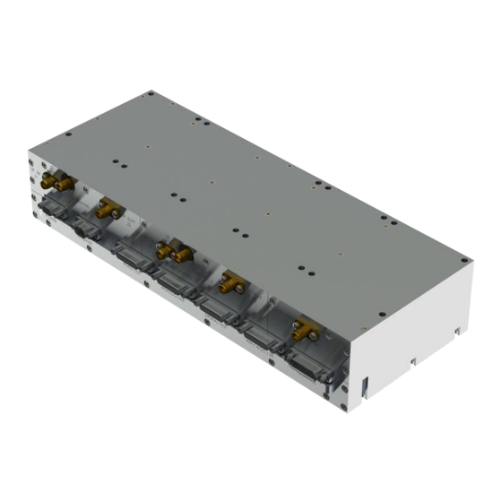
Page 23: Figure 4: 3Rd Generation Compact Rdms™ Receiver-Combiner
Generation Dual Channel Compact RDMS Telemetry Receiver-Combiner Figure 4: 3rd Generation Compact RDMS™ Receiver-Combiner Quasonix, Inc. -
Page 24: Thermal
Glenair MWDM2L-9SCBRP-.150 (Socket) MDM-9 Socket RS-422 Clock/Data Out MWDM2L-25PCBRP-.150 (Plug) MDM-25 Plug Analog Out (Video) MWDM2L-25PCBRP-.150 (Plug) MDM-25 Plug Digital Out (TTL Clock/Data) MWDM2L-25PCBRP-.150 (Plug) MDM-25 Plug AM/AGC/HT MWDM2L-25PCBRP-.150 (Plug) MDM-25 Plug Control (Factory) MWDM2L-25SCBRR2T-.150 (Socket) MDM-25 Socket Quasonix, Inc. -
Page 25: Front Panel Connections
J10-18 J10-22 RS422/Data A_n J10-2 J10-6 J10-10 RS422/Data A_p J10-15 J10-19 J10-23 RS422/Clock B_n J10-3 J10-7 J10-11 RS422/Clock B_p J10-16 J10-20 J10-24 RS422/Data B_n J10-4 J10-8 J10-12 RS422/Data B_p J10-17 J10-21 J10-25 Ground J10-13 50 W SMA MDM-25 Quasonix, Inc. - Page 26 J13-24 Aux Analog B J13-21 J13-23 J13-25 Ground J13-13 Power on J14-20 J14-19 J14-18 J14-15 J14-17 J14-16 J14-24 J14-22 J14-23 J14-12 J14-6 J14-21 J14-8 J14-2 J14-5 J14-9 J14-3 J14-11 J14-10 J14-4 J14-14 3.3V J14-13 J14-7 J14-25 Ground J13-1 Quasonix, Inc.
-
Page 27: Electrical Signals
The CRC™ also provides a 70 MHz IF output for each channel for troubleshooting purposes. These IF outputs are capped with 50 ohm terminators, and these should be left in place unless another 50 ohm load (such as a spectrum analyzer) is connected instead. Quasonix, Inc. - Page 28 The IF input connector is only active if the correct part number is ordered. The metal cap on the connector upon delivery is a dust cap only and is NOT interchangeable with the 50 Ohm termination on the IF output. Do not remove dust caps unless the connector is being used. Quasonix, Inc.
-
Page 29: Operating Instructions
While the Browser Interface works with most modern browsers, the latest version of Firefox or Chrome is recommended. Quasonix recommends running Firefox in Private mode or disabling caching to improve performance. HTML5 compatibility is required. The Browser Interface (BI) provides easy-to-read, real-time status information to the user. -
Page 30: Figure 7: Custom Mdm-25 Ip Reset Connector
IP Reset Connector from the Control port. If this is left in place, the IP address will once again be reset to default. Browse to the About page, and modify the network settings as described in section 5.6.2. Quasonix, Inc. -
Page 31: Browser Interface
URL box. The additional receivers are on the same network but are in use by other users. Figure 10 shows a closeup of the right half of the Network screen with combiners only displayed. Figure 11 shows a closeup of the left side of the Network screen with the Configure and Monitor buttons. Quasonix, Inc. -
Page 32: Figure 9: Network Screen With Multiple Receivers And Active Channels
Generation Dual Channel Compact RDMS Telemetry Receiver-Combiner Figure 9: Network Screen with Multiple Receivers and Active Channels Figure 10: Network Screen, Closeup of Left Side, Combiners Only Quasonix, Inc. -
Page 33: Monitor Screen
The Monitor screen may be accessed via the Monitor buttons on the Network screen, as described previously, or via the Monitor option on the Tool bar, as shown in Figure 12. Figure 12: RDMS™ Browser Interface Tool Bar The unit information displays in the Monitor view, as shown in Figure 13. Quasonix, Inc. -
Page 34: Figure 13: Browser Interface Monitor Screen
Graphical representations of the spectrum • Zero AGC button – For user convenience, this button displays on the Monitor screen and the Configure screen If the user is operating a single-channel receiver, only Channel 1 displays, as shown in Figure 14. Quasonix, Inc. -
Page 35: Figure 14: Monitor Screen For Rdms™ With Only One Channel Available
On, as shown in Figure 15, or displayed in the center of the screen between Channel 1 and Channel 2 when the combiner is Off, as shown in Figure 16. Figure 15: Monitor Screen Partial Status Information Block when Combiner On Figure 16: Monitor Screen Partial Status Information Block when Combiner Off Quasonix, Inc. -
Page 36: Signal Graph And Signal Indicators
Figure 18: Example PCM/FM Eye Pattern Figure 19: Example SOQPSK Constellation To the right of the Signal Graph is the Signal Indicators window, shown in Figure 20. The Signal Indicators window includes the following indicators for each receiver channel: • Signal Strength Quasonix, Inc. -
Page 37: Figure 20: Waveform Graphics With Locked Soqpsk Signal
Note: The integrated Quasonix demodulator can detect and establish signal lock at very low signal levels. Therefore, it is not uncommon to see a red signal strength bar indicator accompanied with a signal lock indicator that is locked. -
Page 38: Figure 21: Signal Graph And Signal Indicators Windows, Zero Agc Rssi Display "Relative
Figure 21: Signal Graph and Signal Indicators Windows, Zero AGC RSSI Display “Relative” 5.2.2 Spectrum Graph Each channel display provides a real-time power spectral density (PSD) plot as it might display on a spectrum analyzer. An example is shown in Figure 22. Quasonix, Inc. -
Page 39: Figure 22: Power Spectral Density Plot Window
If diversity combiner is On, any changes made to one channel will be copied to the other channel so that both channels are synchronized. If diversity combiner is Off, each channel is separate and setting one channel does not copy settings to the other channel. Quasonix, Inc. -
Page 40: Figure 24: Best Channel Indicator Example
(‘1’, ‘C’, and ‘2’ respectively). The color of each character designates the current state of that channel in the best-channel selection process: • Bright green – Best signal; this signal has the highest data quality of all correlating signals, and its quality is directly reflected in the BCS quality bar Quasonix, Inc. -
Page 41: Figure 25: Best Channel Indicator-Combiner
Figure 25 illustrates a good signal for Channel 1 and Channel 2, with the best signal being selected from the Combiner. Figure 25: Best Channel Indicator-Combiner Figure 26 illustrates a good signal for the Combiner and Channel 2, with the best signal being selected from Channel 1. This is an example of all channels being essentially “perfect.” Quasonix, Inc. -
Page 42: Figure 26: Best Channel Indicator-Ch 1
Combiner. In this case, the BCS selects Channel 2, as shown by the circled BCS selection indicator and BCS data quality of 10. Without the BCS, the Combiner output data quality would be less than 6. Figure 28: Best Channel Data Quality Better than Combiner Data Quality Quasonix, Inc. -
Page 43: Figure 29: Best Channel Indicator Off (Grey)
The user may view: • Full Monitor screen • Eye pattern or Constellation only • PSD (spectrum display) only • Combiner display only Examples of each display type are shown in the following figures. Figure 30: Monitor Display Menu Quasonix, Inc. -
Page 44: Figure 31: Monitor Full Display (Default)
Generation Dual Channel Compact RDMS Telemetry Receiver-Combiner Figure 31: Monitor Full Display (Default) Figure 32: Monitor Eye Pattern/Constellation Display Only Quasonix, Inc. -
Page 45: Figure 33: Monitor Psd (Spectrum) Only
Network bandwidth usage is roughly halved as you progress through each setting from High to Low. High is the as-shipped default setting. The receiver continues normal operation if the Monitor screen is temporarily stopped. Quasonix, Inc. -
Page 46: Figure 35: Monitor Combiner Display Only
Diversity combining can be enabled by clicking on the check box in the Combiner field, as shown in Figure 37. Figure 37: Configure Screen, Combiner Section When the combiner is enabled on one channel, the second channel will automatically reflect this change. Quasonix, Inc. -
Page 47: Figure 38: Configuration Screen With Combiner On, Channel 1 Displays
Interface. If the Combiner is On, only Channel 1 displays (Figure 38). Click on any field within the Configure screen to change and save settings for Channel 1, Channel 2, or both channels (Figure 39). Figure 38: Configuration Screen with Combiner On, Channel 1 Displays Quasonix, Inc. -
Page 48: Figure 39: Configuration Screen With Combiner Off, Channel 1 And Channel 2 Display
5.4.2.1 for specific information about Power Ratio. Refer to section 5.4.2.2 for specific information about AQPSK mode. Note: The Equalizer is currently available for use with all modes except STC mode. Figure 40: Configure Basic Settings Window-PCM/FM Mode Quasonix, Inc. -
Page 49: Figure 41: Configure Screen, Messages And Alerts
I data outputs (Clock A and Data A) and Q data outputs (Clock B and Data B). When AQPSK mode is selected, the Configure Basic Settings Window shows two bit rates (Bit Rate and Bit Rate B), as shown in Figure Quasonix, Inc. -
Page 50: Figure 42: Configure Basic Settings Window Aqpsk Mode, Two Bit Rates
Data and Clock Polarity Settings The Data Polarity and Clock Polarity are set by clicking on drop down arrow to display the menu, then selecting the desired option, Normal or Inverted, as shown in the Data Polarity example in Figure 43. Quasonix, Inc. -
Page 51: Figure 43: Settings Window, Data Polarity Selection
(BEP) allows DQE from multiple vendors to interoperate. The Quasonix DQM is based on statistics developed deep inside the demodulator. Bit Error Probability (BEP) is the calculated likelihood that a bit is in error. A very low BEP can be determined from only a few bits. BEP does not require any known data and can be determined quickly and accurately from demodulator statistics. -
Page 52: Figure 45: Dqe Format
(similar to break frequency). To change the DQE, go to the Configure Basic Settings window, then click on the check box next to DQ Encapsulation. The parameter options are Enable (checked) or Disable (unchecked). The default is Disabled (unchecked). Quasonix, Inc. -
Page 53: Figure 46: Configure Basic Settings Window, Dq Encapsulation Checked
LDPC Mode is enabled (SOQPSKLDPC or STCLDPC) or when Reed-Solomon decoding is enabled. • IRIG – Derandomizes data randomized using the IRIG 15-stage randomizer • CCSDS – Derandomizes data randomized using the CCSDS 8-stage block synchronous randomizer Figure 47: Settings Window, Derandomizer Drop Down Menu Quasonix, Inc. -
Page 54: Figure 48: Configure Basic Settings Window-Soqpsk Mode
IF Filter, Output Muting, Muting Timeout, AFC Mode, Best Channel Selector, Time Aligner, and PCM Encoding, as shown in Figure 49. Additionally, the Advanced Settings window shows Video Output parameters, Channel A and Channel B Output, Channel A and Channel B Scale, Tape Output Frequency, and FM De-emphasis (when in PCM/FM mode). Quasonix, Inc. -
Page 55: Figure 49: Advanced Settings Window
When the modulation is set to PCM/FM, the Filter Settings window includes settings for IF and Phase Noise Compensation. In any other mode, only the IF Filter option is available. Quasonix, Inc. -
Page 56: Figure 50: Advanced Settings Window, If Filter Menu
The optimal AFC mode depends on the source and magnitude of the frequency offset. Valid selections are Off, Hold, and Track. In general, Quasonix recommends setting the AFC Mode to Off, if possible. -
Page 57: Figure 51: Advanced Settings Window, Afc Mode Menu
Best Channel Selector The Best Channel Selector option sets the Best Channel Selector value to On or Off. When this option is checked (On), the combiner data output selects the best channel (1, 2, or Combiner) based on DQM. Quasonix, Inc. -
Page 58: Figure 52: Advanced Settings Window, Best Channel Selector Checked
Figure 52: Advanced Settings Window, Best Channel Selector Checked The Best-Channel Selector (BCS) is a revolutionary new feature, unique to the Quasonix RDMS™. Its purpose is to ensure that the back-panel data output from the Combiner is always optimal, even in rare cases where the Pre- Detection Diversity Combiner struggles relative to Channel 1 and Channel 2. -
Page 59: Figure 53: System Block Diagram With Best Channel Selector
When disabled, it remains Off and does not affect the combiner. Clicking on the check box to enable the (combiner) time aligner, as shown in Figure 54, lets it determine when to operate (with no user intervention). Quasonix, Inc. -
Page 60: Figure 54: Advanced Settings Window, Time Aligner Selection Checked
The Quasonix RDMS™ Combiner can perform both phase alignment and time alignment of the Channel 1 and Channel 2 signals. The Time Aligner is capable of correcting up to ±1300 nanoseconds of time skew between channels (about a quarter mile of free-space propagation). -
Page 61: Figure 55: Advanced Settings Window, Pcm Encoding Drop Down Menu
Out outputs the Pre-D signal, and Carrier Only outputs an unmodulated carrier; either of these will be output at the carrier frequency selected by Tape Out Freq (MHz). Figure 56: Advanced Settings Window, Channel A Video Output Drop Down Menu Quasonix, Inc. -
Page 62: Figure 57: Advanced Settings Window, Channel B Video Output Drop Down Menu
By default the video output is 1.0000 V peak-to-peak using a standard deviated NTSC video signal. This setting allows the user to compensate for a system where this is not the case. Figure 58: Advanced Settings Window, Channel A Video Scale Quasonix, Inc. -
Page 63: Channel B Video Scale
SOQPSK or STC modes, as shown in Figure 63 and in Figure 64, or by using Convolutional encoding/Viterbi decoding, and/or ReedSolomon encoding in legacy PSK modes (BPSK, QPSK, OQPSK, AQPSK, AUQPSK, or UQPSK), as shown in Figure 62. Quasonix, Inc. -
Page 64: Ldpc Mode (Soqpskldpc Or Stcldpc Modes Only)
Lower code rates also provide better decoding performance at the cost of increased occupied bandwidth. The optimal code choice for any application may require empirical testing to determine. Quasonix, Inc. -
Page 65: Figure 63: Forward Error Correction Window, When In Soqpskldpc Or Soqpskstc Mode
LDPC encoding is intended to improve performance specifically under harsh conditions, which might have a negative effect on AFC tracking. In general, Quasonix recommends setting the AFC Mode to Off if possible. This recommendation is especially important for the best LDPC performance. Refer to section 5.4.3.5 for more information about AFC Mode. -
Page 66: Viterbi Decoder (K7 Option Required) (Legacy Psk Modes Only)
(variants of QPSK) when using convolutional encoding. The first method is for I and Q data streams to be independently encoded. In this method, two convolutional encoders are used, one for I data and one for Q data, as shown in Figure 66. Quasonix, Inc. -
Page 67: Figure 66: I And Q Data Streams Independently Encoded
In this method, only one convolutional encoder is used for both the I and Q data. Figure 67: I and Q Data from Single Convolutional Encoder The appropriate decoder for this method is selected by setting Convolutional Symbol to Enabled (checked), as shown in Figure 68. Quasonix, Inc. -
Page 68: Reed-Solomon Decoder (K7 Option Required) (Legacy Psk Modes Only)
Therefore, in AQPSK and AUQPSK modes, only the ‘A’ data will be decoded when Reed-Solomon decoding is enabled; ‘B’ data will be output without decoding. Reed-Solomon decoding and Viterbi decoding can be used together or separately. The Reed-Solomon decoder is selected by setting R-S Decoder to Enabled (checked), as shown in Figure 69. Quasonix, Inc. -
Page 69: Interleave Depth (K7 Option Required) (Legacy Psk Modes Only)
Modulation Index Scaling Mode contains four settings: Track, Hold, Off, and Acquire. The RDMS™ automatically adjusts demodulator bandwidth based on the selected/estimated modulation index. However, IF filter bandwidth is not automatically adjusted, even when set to automatic. It is recommended that the Quasonix, Inc. -
Page 70: Modulation Scaling - Track
Note: Whenever the Diversity Combiner is On, any changes made to the Frequency option (even with Frequency Diversity On enabled) causes Modulation Scaling for both channels to be set to Track. Figure 72: Advanced PCMFM Settings Menu, Modulation Scaling – Track Quasonix, Inc. -
Page 71: Modulation Scaling - Hold
When Modulation Scaling is set to Hold, the Mod Scaling indicator on the Monitor screen displays Hold, as shown in Figure 75, indicating the optimal modulation index is set. Figure 74: Advanced PCMFM Settings Menu, Modulation Scaling – Hold Quasonix, Inc. -
Page 72: Modulation Scaling - Off
Monitor screen displays Off, as shown in Figure 77, indicating the optimal modulation index is set. Figure 76: Advanced PCMFM Settings Menu, Modulation Scaling – Off Figure 77: Monitor Screen, Mod Scaling Set to Off Quasonix, Inc. -
Page 73: Modulation Scaling - Acquire
Triggered back to Armed except for setting the mode to Acquire again. 5.4.12.2 Modulation Persistence Modulation Persistence allows the current state of the Modulation Scaling setting to be retained following a power- off cycle. The default value is Off (not checked), as shown in Figure 80. Quasonix, Inc. -
Page 74: Mod Scale Index
Modulation Scale Index field is set to read only, as shown in Figure 81. Use the steps in section 5.4.12.1 to set and save the scaling mode. When the scaling mode is saved as Hold, the Mod Scale Index field changes to an editable Quasonix, Inc. -
Page 75: Phase Noise Compensation
The Phase Noise Compensation (PNC) option is used to set the Phase Noise Compensation value to On, Off, or Auto. Refer to Appendix D in section 12 for detailed information about PNC. Figure 83: Advanced PCMFM Settings Window, Phase Noise Compensation Drop Down Menu Quasonix, Inc. -
Page 76: System Settings
• Antenna Controls • Clock/Data Output Controls • Test Utilities Figure 84: System Settings Window 5.4.13.1 Antenna Controls The Antenna Controls section contains the following parameters for AGC (Automatic Gain Control) and AM, as shown in Figure 85. Quasonix, Inc. -
Page 77: Hypertrack
Note, in a HyperTrack™-equipped receiver, the Sync Detect digital status output is unavailable. Also, when HyperTrack™ is enabled, the Lock Detect digital status output automatically becomes a copy of the HyperTrack™ digital output data. Click on the drop down menu to select Enabled or Disabled, as shown in Figure 86. Quasonix, Inc. -
Page 78: Agc Polarity
10 dB/V and 1.0 V if the scale is set to 20 dB/V. The maximum AGC output voltage is ±5.0 V. To change the AGC Scale value, type the new value, in dB/V, or use the up/down arrows to scroll to the desired value. Figure 88: Antenna Controls Window, AGC Scale Selection Quasonix, Inc. -
Page 79: Agc Time Constant
AGC Freeze is not absolutely necessary to obtain excellent noise figure or G/T readings via the RSSI measurement. Click on the drop down menu to select On or Off, as shown in Figure 90. Figure 90: Antenna Controls Window, AGC Freeze Selection Quasonix, Inc. -
Page 80: Agc Zero Mode
Figure 92. The AM Bandwidth can be set from 5.00 to 50000.00 Hz. 5.4.13.10 AM Polarity AM Polarity is set by clicking on the drop down menu to select the desired value, Positive or Negative, as shown in Figure 92. Quasonix, Inc. -
Page 81: Am Scale
It is common to tune to the C to P band downconverted signal by specifying the C band frequency. In a receiver that also has actual C band receiver capability, an ambiguity develops when a C band frequency is Quasonix, Inc. -
Page 82: Figure 94: Output Controls Window
No DQE – Selecting No DQE bypasses data quality encapsulation • Test Data – Selecting Test Data causes the output of the Data Generator to display on Channel A clock and data Figure 95: Output Controls, Clock/Data Output Channel A Quasonix, Inc. -
Page 83: Figure 96: Output Controls, Clock/Data Output Channel B
Figure 96: Output Controls, Clock/Data Output Channel B 5.4.15 Test Utilities The Test Utilities selections, accessed via the Advanced Menu, as shown in Figure 97, provide access to the following options: • Noise Generator • Data Generator • BERT Quasonix, Inc. -
Page 84: Figure 97: System Settings, Test Utilities
Test Noise - Enables or disables the AWGN generator, as shown in Figure 98 Figure 98: Test Utilities, Noise Generator-Test Noise Drop Down Menu • Noise Level -Sets the noise level to use in the test in dB E , as shown in Figure 99 Quasonix, Inc. -
Page 85: Figure 99: Test Utilities, Noise Generator-Noise Level Selection
Test Data – Enable or disable test data generation, as shown in Figure 101 Figure 101: Data Generator, Test Data Drop Down Menu • Data rate in Mbps – Typing a number in this field sets the data rate in Mbps, as shown in Figure 102 Quasonix, Inc. -
Page 86: Figure 102: Data Generator, Data Rate Selection
Inversion – Set to Normal or Inverted, as shown in Figure 104; when Inverted the data stream is inverted; useful for patterns that are defined as inverted by certain standards, or to compensate for an inversion elsewhere in the system Figure 104: Data Generator, Inversion Drop Down Menu Quasonix, Inc. -
Page 87: Figure 105: Data Generator, Randomization Drop Down Menu
The available BERT settings are: Measurement, (Re)Start BERT, Pattern, Type, Time Limit (s), Bit Limit, Error Limit, Gating, and Restart on Resync. Each setting is described in this section. • Measurement – Enables or disables Bit Error Rate (BER) measurement Quasonix, Inc. -
Page 88: Figure 107: Bert, Bert Measurement Drop Down Menu
PN31 – Pseudorandom pattern 2 -1 bits in length • User Defined • User Defined – A unique binary pattern, between 2 and 32 bits, specified by the person running the test; only available when Pattern is “User Defined” Quasonix, Inc. -
Page 89: Figure 109: Bert, Pattern Drop Down Menu
• Single – Runs the BER measurement one time based on programmed limits • Repeat – Runs the BER measurement until it reaches programmed limits, then repeats the measurement Quasonix, Inc. -
Page 90: Figure 112: Bert, Gating Drop Down Menu
Figure 114: Test Utilities, BERT Status Colored indicators are always grey when inactive, or an associated color during a test. The status display continually updates for the duration of a BER test. • Enabled – Green when enabled Quasonix, Inc. -
Page 91: Figure 115: Test Utilities, Status During Ber Test
Automatic Gain Control (AGC) may be set to zero (0) by clicking on the green Zero AGC button in the Advanced section, shown in Figure 116. One or two buttons are available depending on the number of channels and the combiner mode. Quasonix, Inc. -
Page 92: Figure 116: Advanced Buttons, Zero Agc Button, Separate Channels Or Combiner Active
AGC Zero value displayed, as shown in Figure 117. When AGC is zero, the bar graph is not grey and the AGC Zero value is displayed, as shown in Figure 118. Figure 117: Monitor Screen, Signal Strength Grey – AGC Not Zero Quasonix, Inc. -
Page 93: Figure 118: Monitor Screen, Signal Strength Not Grey - Agc Zero Value Displayed
A value above zero indicates how strong the signal is above no input • “*** dBm” displayed (Figure 21) indicates AGC is not zeroed and the value is invalid • A small “r” displayed next to the Signal Strength label indicates AGC Zero Relative was selected Quasonix, Inc. -
Page 94: Figure 119: Signal Graph And Signal Indicators Windows, Zero Agc Rssi Display "Relative
If the user intends to immediately restart the RDMS, it is important to wait until the indication that the unit is offline is received. This takes about 30 seconds, and is typically indicated by an “Unable to connect” message in the browser. Quasonix, Inc. -
Page 95: Figure 121: Advanced Buttons, Shutdown Hardware Button
It is similar to saving a preset, but instead of saving the settings to a preset and recalling the preset, the current settings are just saved. If power is lost to the receiver, the saved settings are still set upon power up. Quasonix, Inc. -
Page 96: Figure 123: Advanced Buttons, Save Receiver Settings Button
Accessed from the Presets option in the Tool Bar, Saved Presets screen, shown in Figure 125, allows the user to save and load settings stored on the RDMS™ receiver. Closeups of the right and left side of the Presets screen are shown in Figure 126 and Figure 127. Figure 125: Presets Screen Quasonix, Inc. -
Page 97: Figure 126: Presets Screen, Closeup Of Left Side
View/Modify button next to the desired preset. When the user clicks on a View/Modify button, the Preset: View or Modify Preset screen opens, as shown in Figure 128. The contents and layout of this screen is similar to the Configure screen. Quasonix, Inc. -
Page 98: Figure 128: Preset: View Or Modify Preset Screen
Frequency and Bit Rate, typing the number directly or using up/down scroll arrows to select the desired value. New options are provided to the user when certain options are selected, for example, Frequency Diversity and Time Aligner are only available after Combiner is enabled and saved. Quasonix, Inc. -
Page 99: Figure 130: Preset: View Or Modify Preset Screen, Information Successfully Saved Message
Figure 130: Preset: View or Modify Preset Screen, Information Successfully Saved Message When the user clicks on the Presets option in the Menu bar, the Saved Presets screen displays clearly showing the new preset, as shown in Figure 131. Quasonix, Inc. -
Page 100: Figure 131: Saved Presets Screen With New Preset Added
Loading a preset configuration is a quick way to set up an RDMS™ with specific settings. The RDMS™ has eight (8) default configurations pre-loaded and ready to use on the receiver. As shown in the previous section, the user may set up and save other configurations for later reuse. Quasonix, Inc. -
Page 101: Figure 133: Presets Option On Tool Bar
In addition to displaying the system information, this screen is also used to add a Rack Alias, if desired. Type a new name into the Rack Alias field, as shown in Figure 137, then click on the Rename button. Quasonix, Inc. -
Page 102: Figure 136: System Information Screen
Figure 136: System Information Screen Figure 137: System Information Screen, Additional Information 5.6.1 Firmware Updates The CRC supports a remote Firmware Update via the browser interface. This feature relies on an encrypted and signed firmware update file provided by Quasonix upon release. Quasonix, Inc. -
Page 103: Figure 138: Browser Interface, About
Compact RDMS Telemetry Receiver-Combiner To perform a network update: Obtain a firmware update file from Quasonix. Using a web browser, navigate to the About page of the RDMS Browser Interface, as shown in Figure 138. Figure 138: Browser Interface, About... -
Page 104: Figure 140: Firmware Update, Procedure And Notes
Telemetry Receiver-Combiner On the Firmware Update screen, review the Procedure and Notes, as shown in Figure 140. Click on the Browse button to select the update file provided by Quasonix. Figure 140: Firmware Update, Procedure and Notes After the selected filename displays, click on the Load Update File button to transfer the file to the RDMS. -
Page 105: Figure 141: Firmware Update, Upload Status
After the file has been transferred, review the updated Notes, as shown in Figure 142. Click on the Begin Update button to start the update. Note: If Autostart was selected previously, this step is automated. No further input is required unless an error is encountered. Quasonix, Inc. -
Page 106: Figure 142: Firmware Update, File Selected-Ready To Update
Do not power off the RDMS during the update • Do not close the browser window during the update • During the update, the status and approximate time remaining will display, as shown in Figure 143. Figure 143: Firmware Update In Progress, Status Quasonix, Inc. -
Page 107: Figure 144: Firmware Update Complete
Following the update, the RDMS returns to normal operating mode and all parameters are reset to system defaults. 10. Navigate to the About screen, as shown in Figure 145, to verify that the System Version matches the firmware update version. Quasonix, Inc. -
Page 108: Figure 145: About Screen, System Information
If the update fails for any reason, an information screen displays, as shown in Figure 146. Follow the instructions on the screen to retry the update or return to normal RDMS operation. An error code is provided and should be noted for use in correspondence with Quasonix. Figure 146: Firmware Update Failed Information Screen... -
Page 109: Figure 147: System Information Screen, Modify Network Settings Button
Network Settings button displays under the Interfaces portion of the screen, as shown in Figure 147. Figure 147: System Information Screen, Modify Network Settings Button Click on the Modify Network Settings button to display the Network Settings Page, as shown in Figure 148. Figure 148: Network Settings Page Quasonix, Inc. -
Page 110: Figure 149: System Information Screen, Monitor Page Default Update Rate Field
The Help option on the Footer Tool bar, provides a link to the 3rd Gen Dual Channel Compact RDMS Receiver- Combiner Installation and Operation manual, an RDMS API User Guide, as well as contact information for Quasonix. The Help screen is shown in Figure 151. Quasonix, Inc. -
Page 111: Figure 151: Help Screen
Generation RDMS receiver uses a built-in web server to provide monitoring and control. Multiple users may access the receiver. To minimize configuration or control conflicts, the Browser Interface alerts users of potential conflicts. Users may choose to override controls to provide access to specific pages. Figure 152: Page Access Management Screen Quasonix, Inc. -
Page 112: Figure 153: Page Access Error Message
Information by clicking on the check box associated with each option. The Export Configuration button activates the download of the selected items into a single JSON type file that may be imported and read by the same, or other, RDMS Receivers. Figure 154: Export Configuration Screen Quasonix, Inc. -
Page 113: Figure 155: Import Configuration Screen
After the import file is selected, the Import Configuration screen allows the selection of specific items to be immediately copied to the current device, as shown in Figure 156. Note that any settings on the receiver in the selected areas will be overwritten. This includes the Current Configuration. Quasonix, Inc. -
Page 114: Figure 156: Import Configuration Selection Window
Generation Dual Channel Compact RDMS Telemetry Receiver-Combiner Figure 156: Import Configuration Selection Window Quasonix, Inc. -
Page 115: Table 6: Rdms Ber Specifications
Table 6: RDMS BER Specifications Maximum E (dB) PCM/FM, Tier 0 SOQPSK-TG, Tier I Multi-h CPM, Tier II 11.0 11.5 12.5 10.0 13.0 13.5 11.0 14.5 14.5 Typical BER performance, plotted in Figure 157, is significantly superior to that tabulated above. Quasonix, Inc. -
Page 116: Figure 157: Ber Performance For Tier 0, I, And Ii
The Compact RDMS™ offers very fast, reliable acquisition, even at very low signal to noise ratio. Synchronization time is a function of modulation type and IF frequency error. Typical SOQPSK results (from 10,000 synchronization trials) are shown in Figure 158. Quasonix, Inc. -
Page 117: Figure 158: Synchronization Time At Various Signal-To-Noise Ratios
Generation Dual Channel Compact RDMS Telemetry Receiver-Combiner Figure 158: Synchronization Time at Various Signal-to-Noise Ratios Quasonix, Inc. -
Page 118: Table 7: Band Configuration Codes
Base 1534.5 1750.0 Base 1850.0 2200.0 Base 2394.5 4400.0 Base 5150.0 400.0 Lower L Upper L Freq. Code Legend: Frequency Gap Standard (Base) Frequency Range Extended Frequency Range (available by selecting Extended Tuning = 1 in part number) Quasonix, Inc. - Page 119 Additional Band Codes Two additional band codes are available: • Band Code 7: Through the IF Input: 70 MHz through SAW filters, 0.075 MHz-20 MHz, 70 MHz • Band Code T: 2025.0 MHz to 2110.0 MHz standard range Quasonix, Inc.
-
Page 120: Figure 159: 70 Mhz If Module In 2" X 3" Chassis
MHz, 14 MHz, and 28 MHz. The measured responses of the optional filters are shown in Figure 162 and Figure 163. Contact Quasonix for information about the optional filters. Based on the receiver’s high level of integration, the proper IF filter is automatically selected based on the current mode and bit rate settings of the demodulator. -
Page 121: Figure 160: 70 Mhz If Module In 2" X 3" Chassis Saw Filter Responses, Narrow Group (10 Mhz Span)
Generation Dual Channel Compact RDMS Telemetry Receiver-Combiner Figure 160: 70 MHz IF Module in 2” x 3” Chassis SAW Filter Responses, Narrow Group (10 MHz Span) Quasonix, Inc. -
Page 122: Figure 161: Saw Filter Responses, Wide Group (Plotted On 100 Mhz Span)
Generation Dual Channel Compact RDMS Telemetry Receiver-Combiner Figure 161: SAW Filter Responses, Wide Group (Plotted on 100 MHz Span) Quasonix, Inc. -
Page 123: Figure 162: Optional Saw Filter Responses For 70 Khz To 6 Mhz
Generation Dual Channel Compact RDMS Telemetry Receiver-Combiner Figure 162: Optional SAW Filter Responses for 70 kHz to 6 MHz Quasonix, Inc. -
Page 124: Figure 163: Optional Saw Filter Responses For 14 Mhz And 28 Mhz
Generation Dual Channel Compact RDMS Telemetry Receiver-Combiner Figure 163: Optional SAW Filter Responses for 14 MHz and 28 MHz Quasonix, Inc. - Page 125 Generation Dual Channel Compact RDMS Telemetry Receiver-Combiner 8 Maintenance Instructions The Dual Channel Compact RDMS™ Receiver-Combiner requires no regular maintenance, and there are no user- serviceable parts inside. Please consult the factory for any maintenance, upgrade, or repair requirements. Quasonix, Inc.
- Page 126 Quasonix. Quasonix shall not be liable for a breach of the warranty set forth in this Limited Warranty unless: (i) the customer gives written notice of the defect, reasonably described, to Quasonix’s Contracts Administrator within thirty (30) days of the time when customer discovers or ought to have discovered the defect and obtains a Return Materials Authorizations (“RMA”) number;...
- Page 127 Products; (c) as a result of a failure to follow the instructions in the Operations & Maintenance Manual (d) by the use of parts not manufactured or sold by Quasonix; or (e) by modification or service by anyone other than (i) Quasonix, (ii) an Quasonix authorized service provider, or (iii) your own installation of end-user replaceable Quasonix or Quasonix approved parts if available for the Products in the servicing country.
- Page 128 Telemetry Receiver-Combiner 10 Technical Support and RMA Requests In the event of a product issue, customers should contact Quasonix via phone (1-513-942-1287) or e-mail (support@quasonix.com) to seek technical support. If the Quasonix representative determines that the product issue must be addressed at Quasonix, a returned materials authorization (RMA) number will be provided for return shipment.
-
Page 129: Table 8: Recommended Am/Agc Settings
1000 / ScanRate 5 * ScanRate Conical scan 850 / ScanRate 5 * ScanRate E-scan 1000 / ScanRate 10 * ScanRate E-scan 850 / ScanRate 10 * ScanRate In Table 8, ScanRate is the antenna scan rate in Hz. Quasonix, Inc. - Page 130 At the recommended settings, AM phase delay is approximately 30 degrees for typical conical scan and e-scan scan rates. If AGC Compensation is enabled, the AGC Time Constant and AM Bandwidth should both be set only as indicated in Table 8. Quasonix, Inc.
-
Page 131: Figure 164: Ideal Pcm/Fm Phase Tree (H = 0.7)
The Phase Tree shown in Figure 164, shows all of the possible paths the phase trajectory can take over a period of seven bits. Figure 165 shows the two unique paths, based on whether the second bit is a 1 or 0. Figure 164: Ideal PCM/FM Phase Tree (h = 0.7) Quasonix, Inc. -
Page 132: Figure 165: Phase Trajectory Never Forgets
High phase noise can reduce the trellis detection gain because phase noise corrupts the tree. The following figures illustrate the differences in trellis detection gain depending on the amount of phase noise introduced. Figure 166: Trellis Detection Gain with Zero to Minimum Phase Noise Quasonix, Inc. -
Page 133: Figure 167: Trellis Detection Gain With Significant To Severe Phase Noise
AGC is green.) • The eye pattern NEVER looks “clean,” as in Figure 168 • Symptoms get worse when the transmitter is under vibration • Symptoms get worse at low bit rates Quasonix, Inc. -
Page 134: Figure 168: "Clean" Eye Pattern
If you know the brand and type of transmitter, these tips can help determine when to use PNC. If your transmitter was manufactured by these companies, PNC should be OFF: • Quasonix – guaranteed • Nova Engineering – highly likely •... -
Page 135: Figure 169: Frame Format With Sfic Insertion Enabled
13 Appendix C - PCM Framer/Deframer Function Quasonix RDMS™ receivers recognize PCM frames as defined by IRIG 106-17 Chapter 4 and Appendix 4-A. The receiver can provide basic processing of a large subset of possible frame configurations, including sync word detection, subframe ID checking, and data extraction from the frame structure (without decommutation). - Page 136 BERT to measure link performance. The RDMS™ receiver can output PCM frame lock and/or SFID valid indications on the DEMOD_LOCK and/or ONES_DETECT back-panel outputs. Refer to the RDMS™ data sheet for more information about these outputs. Quasonix, Inc.
-
Page 137: Table 9: Pcm/Fm Factory Reset Values
DQ Encapsulation (if available) Disabled AGC Scale Derandomizer Disabled AGC Time Constant Differential Decoder AGC Zero Mode Manual Modulation Scaling Acquire AM Bandwidth Modulation Persist AM Polarity Normal IF Filter Auto AM Scale Video De-emphasis AGC Compensation Enabled Quasonix, Inc. -
Page 138: Table 10: Soqpsk Factory Reset Values
Normal Derandomizer Disabled Differential Decoder Enabled IF Filter Auto Downconvert Antenna Disabled AGC Zero Mode Manual Convolutional Decoder Lock Output Polarity Active High NRZ Encoding Output Control Default Output Muting Disabled Phase Noise Compensation Disabled Tape Output Disabled Quasonix, Inc. -
Page 139: Table 11: Multi-H Cpm Factory Reset Values
Data Polarity Normal Derandomizer Disabled Differential Decoder IF Filter Auto Downconvert Antenna Disabled AGC Zero Mode Manual Convolutional Decoder Lock Output Polarity Active High NRZ Encoding Output Control Default Output Muting Disabled Phase Noise Compensation Disabled Tape Output Disabled Quasonix, Inc. -
Page 140: Table 12: Qpsk Factory Reset Values
Derandomizer Disabled Differential Decoder IF Filter Auto Downconvert Antenna Disabled AGC Zero Mode Manual Convolutional Decoder Disabled Lock Output Polarity Active High NRZ Encoding NRZ-L Output Control Default Output Muting Disabled Phase Noise Compensation Disabled Tape Output Disabled Quasonix, Inc. -
Page 141: Table 13: Multi-H Cpm Factory Reset Values
Clock Polarity Normal Data Polarity Normal Derandomizer Disabled Differential Decoder IF Filter Auto Downconvert Antenna Disabled Enabled Convolutional Decoder Lock Output Polarity Active High NRZ Encoding Output Control Default Output Muting Disabled Phase Noise Compensation Disabled Tape Output Disabled Quasonix, Inc. -
Page 142: Figure 170: Firefox Options Interface
In order to instruct the web browser to ‘trust’ the TLS certificate presented by the RDMS during an HTTPS Browser Interface connection, the Quasonix Root Authority Certificate must be imported into the browser or operating system’s Certificate Store. The instructions for this vary by browser and are presented below. -
Page 143: Figure 171: Firefox Certificate Manager
Telemetry Receiver-Combiner Figure 171: Firefox Certificate Manager Click on the Import… button. A File Browser displays. Select the Quasonix Root Authority file obtained from Quasonix, then click on the Open button. The Downloading Certificate window displays, as shown in Figure 172. -
Page 144: Figure 173: Firefox Certificate Viewer-Quasonix Root Ca
Compact RDMS Telemetry Receiver-Combiner Figure 173: Firefox Certificate Viewer-Quasonix Root CA 10. Scroll through the Certificate Names in the Authorities tab of the Certificate Manager to ensure “Quasonix, Inc.” is in the list, as shown in Figure 174. Quasonix, Inc. -
Page 145: Edge, Internet Explorer, And Chrome
Generation Dual Channel Compact RDMS Telemetry Receiver-Combiner Figure 174: Firefox Certificate Manager with Quasonix Root CA Added 11. Using Firefox, browse to https://RDMS_IP, where RDMS_IP is the IP address of the RDMS. 15.2 Edge, Internet Explorer, and Chrome To add a certificate to Edge, Internet Explorer, and Chrome, use the Windows Certificate Browser tool. After a certificate has been added to the system, it is available for use in Edge, Internet Explorer, and Chrome. -
Page 146: Figure 175: Internet Properties, Content Tab
Generation Dual Channel Compact RDMS Telemetry Receiver-Combiner Figure 175: Internet Properties, Content Tab 14. Click on the Certificates button. The Certificates screen displays. Click on the Trusted Root Certification Authorities tab, as shown in Figure 176. Quasonix, Inc. -
Page 147: Figure 176: Certificates Screen
Generation Dual Channel Compact RDMS Telemetry Receiver-Combiner Figure 176: Certificates Screen 15. Click on the Import… button to start the Certificate Import Wizard. The Wizard is shown in Figure 177. Figure 177: Windows Certificate Import Wizard Quasonix, Inc. -
Page 148: Figure 178: Windows Certificate Import Wizard-Browse
Telemetry Receiver-Combiner 16. Click on the Next button. Click on the Browse button under File to Import. 17. Select the Quasonix Root Authority file obtained from Quasonix. Click on the Next button. Figure 178: Windows Certificate Import Wizard-Browse 18. Select “Place all certificates in the following store.”... -
Page 149: Figure 179: Windows Certificate Import Wizard-Choose Certificate Store
20. Click on the Finish button. A message displays “The import was successful.” Click on the OK button. 21. View the list of Certificates under Trusted Root Certification Authorities, and verify that Quasonix Root CA is listed, as shown in Figure 180. -
Page 150: Figure 180: Certificates, Quasonix Certificate Imported
Generation Dual Channel Compact RDMS Telemetry Receiver-Combiner Figure 180: Certificates, Quasonix Certificate Imported 22. Using Edge, Internet Explorer, or Chrome, browse to https://RDMS_IP, where RDMS_IP is the IP address of the RDMS. Quasonix, Inc. -
Page 151: Appendix F - Acronym List
Data Quality Data Quality Encapsulation Data Quality Metric FPGA Field Programmable Gate Array Intermediate Frequency Internet Protocol kbps Kilobits per second Kilohertz Liquid Crystal Display LDPC Low Density Parity Check Mbps Megabits per second Snap on subminiature connector Quasonix, Inc. - Page 152 Shaped Offset Quadrature Phase Shift Keying Shaped Offset Quadrature Phase Shift Keying –Telemetry Group SOQPSK-TG Space-Time Coding Tracking Loop Transistor Transistor Logic User Datagram Protocol UQPSK Unbalanced Quadrature Phase Shift Keying Universal Serial Bus Voltage Alternating Current Voltage, Direct Current Wide Area Network Quasonix, Inc.
Need help?
Do you have a question about the Compact RDMS Telemetry Receiver-Combiner and is the answer not in the manual?
Questions and answers