
Subscribe to Our Youtube Channel
Related Manuals for RS PRO RSDM-906X Series


Summary of Contents for RS PRO RSDM-906X Series
- Page 1 User Manual RSDM-906X series Stock number: 1919720 RSDM-9061 1919721 RSDM-9060 rspro.com...
-
Page 3: Table Of Contents
Table of Contents SAFETY INSTRUCTIONS ........6 GETTING STARTED ........11 Characteristics ............12 Front Panel Overview ..........14 Rear Panel Overview ..........20 Status Bar ..............24 Set Up ..............27 BASIC MEASUREMENT........29 Basic Measurement Overview ........30 AC/DC Voltage Measurement ........ - Page 4 DIGITAL I/O ..........137 Digital I/O Overview ..........138 Application: Compare Mode........142 Application: 4094 / User Mode ......150 Application: External Trigger ........158 SYSTEM & FIRMWARE ........ 160 View System Info ........... 161 Firmware Update ........... 162 MENU SETTING .......... 165 Configure System ...........
- Page 5 Dimensions ............409 Declaration of Conformity ........410...
-
Page 6: Safety Instructions
AFETY INSTRUCTIONS This chapter contains important safety instructions that you must follow when operating the RSDM-9060/9061 and when keeping it in storage. Read the following before any operation to insure your safety and to keep the RSDM- 9060/9061 in the best possible condition. Safety Symbols These safety symbols may appear in this manual or on the instrument. - Page 7 Safety Guidelines Make sure that the voltage input level does not General exceed DC1000V/AC750V. Guideline Make sure the current input level does not CAUTION exceed 10A. Do not place heavy objects on the instrument. Avoid severe impact or rough handling that ...
- Page 8 AC Input voltage: 100/120/220/240 V AC Power Supply ±10%, 50Hz / 60Hz / 400Hz ±10% WARNING The power supply voltage should not fluctuate more than 10%. Connect the protective grounding conductor of the AC power cord to an earth ground to prevent electric shock.
- Page 9 Location: Indoor, no direct sunlight, dust free, Operation almost non-conductive pollution (Note below) Environment Humidity: < 30°C: < 80%RH (non-condensing) 30°C~40°C: <70%RH (non-condensing) >40°C: <50%RH (non-condensing) Altitude: <2000m (Note) EN 61010-1:2010 specifies pollution degrees and their requirements as follows. The RSDM-9060/9061falls under degree 2. Pollution refers to “addition of foreign matter, solid, liquid, or gaseous (ionized gases), that may produce a reduction of dielectric strength or surface resistivity”.
- Page 10 Power cord for the United Kingdom When using the function generator in the United Kingdom, make sure the power cord meets the following safety instructions. NOTE: This lead/appliance must only be wired by competent persons WARNING: THIS APPLIANCE MUST BE EARTHED IMPORTANT: The wires in this lead are coloured in accordance with the following code: Green/ Yellow:...
-
Page 11: Getting Started
However as RS PRO continues to improve its products, changes can occur at any time without notice. Please see the RS PRO website for the latest information and content. Characteristics ............12 Accessories ..................13 Front Panel Overview .......... -
Page 12: Characteristics
Characteristics The RSDM-9060/9061 is a portable, dual-display digital multimeter suitable for a wide range of applications, such as production testing, research, and field verification. The highest DCV accuracy: Performance RSDM-9061: 35ppm RSDM-9060: 75ppm The highest current: RSDM-9061: 10A RSDM-9060: 3A The highest voltage: 1000V ... -
Page 13: Accessories
Graph Display: BarMeter, TrendChart, Histogram USB device/RS232/GPIB(optional)/LAN for Interface remote control 9-pin Digital I/O port USB device port supports USBCDC and USBTMC USB Host Excel Addins Software DMM-VIEWER2 Accessories Standard Accessories Part number Description CD-ROM UM, Software, Driver... -
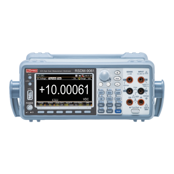
Page 14: Front Panel Overview
Front Panel Overview RSDM-9060 RSDM-9061 Item Description ESC (Escape) Key Print screen / Data log Key USB Host Port Power Switch rspro.com... - Page 15 Function keys (F1 through F6, functions vary per modes) Measurement Keys AC/DC Current Input Terminals (10 A terminal available on RSDM-9061 only) Front/Rear Input Switch (RSDM-9061 only) HI and LO Input Terminals HI and LO Input Terminals Range Selection Keys Knob key Arrow Keys Main Display...
- Page 16 There are 4 rows in total of both basic and Measurement advanced measurement keys deployed on the Keys front panel. The 6 keys have varied functions per different Function Keys settings. Scrolls the knob to select parameters Knob Key in various setting pages. Press the key until click to confirm setting.
-
Page 17: Measurement Keys (Basic)
Accepts ground (COM) line in all Input LO Terminal measurements except the sense line in 4W Resistance. The maximum withstand voltage between this terminal and earth is 500Vpk. Used as an input port for all Input HI measurements except for DC/AC Terminal Current measurements. -
Page 18: Measurement Keys (Advanced)
Shift → ACV (ACI) Measures AC Current Measures DC Voltage. Shift → DCV Measures DC Current (DCI) Measures 2-wire Resistance. Ω2W (Resistance) Shift → Ω2W Measures 4-wire Resistance. (Ω4W Resistance) Tests Continuity. (Continuity) Tests Diode. Shift → (Diode Measures Frequency FREQ (Frequency) Measures Capacitance. - Page 19 Activates the Hold function. Hold Manually sets the parameters for Shift → Hold the Hold measurement. (Hold#) Activates the Trigger function. TRIG (Trigger) Manually sets the parameters for Shift → TRIG the Trigger function. (TRIG#) Enters the setting pages in various Menu Menus.
-
Page 20: Rear Panel Overview
Rear Panel Overview RSDM-9060 RSDM-9061 Item Description 3A Current Terminal Fuse 3A Current Terminal (RSDM-9061 only) RS-232 Interface Connector USB Interface Connector (B Type) rspro.com... - Page 21 Ethernet (LAN) Connector GPIB Connector (optional) AC Mains Line Voltage Selector and Fuse Socket AC Mains Input (Power Cord Socket) Fan Vents DIGITAL I/O Connector HI and LO Input Terminals (RSDM-9061 only) HI and LO Sense Terminals (RSDM-9061 only) Accepts the power cord. AC Power Cord Socket 100/120/220/240V ±10%, 50Hz / 60Hz /400Hz ±10%.
- Page 22 Accepts a digital I/O cable for Digital I/O port the Hi/Lo limit tests; DB-9 pin, female connector. For digital I/O details. Accepts an optional GPIB card. Optional GPIB port For GPIB details. For heat ventilation when Fan Vents machine is under operation. Accepts LO sense line in 4W Sense LO resistance measurement.
- Page 23 Holds the current fuse: T3.15A, DC/AC 3.15A 500V , 5*20mm Input Current Fuse For fuse replacement details.
-
Page 24: Status Bar
Status Bar Identify each icon within the top status bar. Background Status Bar Display 8 9 0 A Item Description Local/Remote control icon RS-232/USB-CDC/USB-TMC/LAN/GPIB interface icon Error icon for commands from remote control Rear panel switch icon Shift key identification icon The first and second function menu switch icon Digital I/O mode icon (User/4094) USB flash drive connection icon... - Page 25 It indicates RS-232 interface is activated. RS-232 It indicates USB - CDC interface is USB - CDC activated. It indicates USB - TMC interface is USB - TMC activated. It indicates LAN interface is activated. It indicates GPIB interface is activated. GPIB It indicates error occurs in commands.
- Page 26 It indicates the Save Reading mode is Flash Drive – ready for the connected flash drive. Save Reading It indicates something error occurs and Flash Drive – thus flash drive fails to connect to unit. Failure It indicates sound of beep is enabled. Sound –...
-
Page 27: Set Up
Set Up Horizontal/Tilt/Vertical Applications Pull out the handle sideways and rotate it clockwise for the applications below. Horizontal Tilt Place the unit horizontally. Rotate the handle for tilt stand. Vertical Place the handle vertically for hand carry. -
Page 28: Power Up
Power Up 1. Ensure the correct line voltage is Steps clearly shown on the fuse socket (240V in the right figure for example). If not, see page 351 to set the proper line voltage and fuse. 2. Connect the power cord to the AC Voltage input. -
Page 29: Basic Measurement
ASIC MEASUREMENT Basic Measurement Overview ......... 30 Refresh Rate ..................30 Automatic (Internal)/Single Triggering ........... 32 AC/DC Voltage Measurement ........34 Select Voltage Range ............... 35 General Voltage Setting ..............36 Voltage Conversion Table ..............40 Crest Factor Table ................41 AC/DC Current Measurement ......... -
Page 30: Basic Measurement Overview
Basic Measurement Overview Basic measurement refers to the several types of Background measurements assigned to the upper 2 row keys on the front panel. AC Voltage Measurement type DC Voltage AC Current DC Current Ω 2W/ Ω 4W 2-wire and 4-wire Resistance Continuity/Diode Frequency/Capacitance FREQ... - Page 31 Continuity / Diode 60/s, 100/s, 400/s 1s, 100ms, 10ms Frequency & Period Capacitance 5/s, 20/s, 60/s Temperature is applicable to RSDM-9060, whilst is specifically Note for RSDM-9061. Press the left or right arrow keys to Selection change the refresh rate. Procedure You can also press the F2 (Speed) key to select a desired rate for...
-
Page 32: Automatic (Internal)/Single Triggering
Reading indicator The reading indicator , which is located in the lower-right corner of display, flashes according to the defined refresh rate setting. Reading Indicator Automatic (Internal)/Single Triggering By default, the RSDM-9060/9061 automatically Overview triggers according to the refresh rate. See the previous page for refresh rate setting details. - Page 33 Press and hold the TRIG key for 2 Automatic seconds to return to the (Internal) Trigger Automatic (Internal) Trigger. (Press & hold for 2 seconds) Indicator Auto (Internal) Trigger Mode Single triggering is not supported for capacitance Note measurements.
-
Page 34: Ac/Dc Voltage Measurement
AC/DC Voltage Measurement 0 ~ 750V Voltage type 0 ~ 1000V Press the ACV key or DCV key to Activate ACV/ measure AC or DC voltage, respectively. The mode will switch to ACV, DCV mode ACV/DCV mode immediately. See the figure below for example. display appears DC or AC Voltage Indicates DC or AC Voltage mode... -
Page 35: Select Voltage Range
Connect the test lead Connect the test between the Input HI lead and measure and Input LO terminals. The display updates the reading. Select Voltage Range To turn the automatic range selection Auto range On/Off, press the Auto key. Press the “+” or the “-” key to select the Manual range range. -
Page 36: General Voltage Setting
For more detailed parameters, see the specifications Note on page 353. General Voltage Setting DCV: F2 (Speed) key to select refresh rate Press the F1 ~ F5 key to select the desired rate. Press the F6 (More 1/2) key for next page with more options as the figure shown below. - Page 37 from affecting measurement accuracy. With autozero disabled (Off), the RSDM-9060/ 9061 measures the offset once and subtracts the offset from all subsequent measurements. When turning On the Auto Zero, the Display display shows an icon indicating the Auto Zero mode is currently being activated.
- Page 38 Vs = ideal voltage of DUT Rs = input impedance of DUT Ri = input impedance of RSDM-9060/ 9061 (either 10M or 10G available (Hi-Z)) Deviation (%) = Rs/(Rs+Ri) * 100 When “Auto” is selected, the display Display shows an icon indicating the Auto mode is currently being activated.
- Page 39 The equation of DCV ratio is like the following mathematical calculation: See the above equation from which DC Reference Voltage indicates the measured voltage from the Sense terminals. Display DCV Ratio Reading Reference Input Voltage Voltage Reading Reading From the screenshot above for example, the INP: +00.86308V (input voltage) is divided by the REF: +00.85414V (reference voltage), and...
-
Page 40: Voltage Conversion Table
Voltage Conversion Table This table shows the relationship between AC and Background DC reading in various waveforms. Waveform Peak to Peak AC (True RMS) Sine 2.828 1.000 0.000 PK-PK Rectified Sine 1.414 0.435 0.900 (full wave) PK-PK Rectified Sine 2.000 0.771 0.636 (half wave) -
Page 41: Crest Factor Table
Crest Factor Table Crest factor is the ratio of the peak signal Background amplitude to the RMS value of the signal. It determines the accuracy of AC measurement. If the crest factor is less than 3.0, voltage measurement will not result in error due to dynamic range limitations at full scale. -
Page 42: Ac/Dc Current Measurement
AC/DC Current Measurement The RSDM-9061, with front/rear input terminals, Background has two input terminals for current measurement: the 3A terminal for current less than 3A and a 10A terminal for measurements up to 10A, which can measure between 3 ~ 10A for both AC and DC current. -
Page 43: Select Current Range
000.03 mAAC Indicates the exact measured value Connect the test lead Connect the test between the 3A lead and measure terminal and the Input LO terminal or DC/AC 10A terminal and the Input LO terminal, depending on the input current. The display updates the reading. - Page 44 Press the “+” or the “-” key to select the Manual range range. The AUTO indicator turns to indicating Manual range selection. If the appropriate range is unknown, select the highest range. You can also press F1 (Range) key to select a range for the measurement.
-
Page 45: General Current Setting
General Current Setting DCI: F2 (Speed) key to select the rate Press the F1 ~ F5 key to select the desired rate Press the F6 (More 1/2) key for next page with more options as the figure shown below. ACI: Press the F1 ~ F3 key to select the desired rate Background Autozero provides the F3 (Auto Zero) key... - Page 46 9060/9061 measures the offset once and subtracts the offset from all subsequent measurements. Display When turning On the Auto Zero, the display shows an icon indicating the Auto Zero mode is currently being activated. rspro.com...
-
Page 47: 2W/4W Resistance Measurement
2W/4W Resistance Measurement 2-wire OHM Uses the standard Input HI-LO Measurement terminals. Recommended for type measuring resistances larger than 1kΩ. 4-wire OHM Compensates the test lead effect using the 4W compensation terminals (SENSE HI/LO terminals), in addition to the standard Input HI-LO terminals. Recommended for measuring sensitive resistances smaller than 1kΩ. -
Page 48: Select Resistance Range
For 2W measurement, connect the test leads Connect the test between the Input HI terminal and the LO lead and measure terminal. For 4W measurement, connect the test leads between the Input HI terminal and the LO terminal, as the way to 2W measurement. Also, connect another sense leads between the SENSE LO and HI terminals. -
Page 49: General Resistance Setting
Press the F6 (More 1/2) key for next page with more options as the figure shown below. Range Resolution Full scale Selectable Resistance Ranges 100Ω 0.1mΩ 119.9999Ω 1kΩ 1mΩ 1.199999kΩ 10kΩ 10mΩ 11.99999kΩ 100kΩ 100mΩ 119.9999kΩ 1MΩ 1Ω 1.199999MΩ 10MΩ 10Ω... - Page 50 measures the offset following each measurement. It then subtracts that measurement from the preceding reading. This prevents offset voltages present on the RSDM-9060/9061’s input circuitry from affecting measurement accuracy. With autozero disabled (Off), the RSDM-9060/9061 measures the offset once and subtracts the offset from all subsequent measurements.
-
Page 51: Continuity Test
Continuity Test The continuity test checks that the resistance in the Background DUT is low enough to be considered continuous (of a conductive nature). Activate continuity test Press the key to activate continuity testing. The mode will switch to continuity testing Continuity mode display appears immediately. - Page 52 Connect the test lead Connect the test between the Input HI lead and measure terminal and the LO terminal. The display updates the reading. Press the F1 ~ F3 key to select the F2 (Speed) key to desired rate select the rate. Background Autozero provides the F3 (Auto Zero) key most accurate...
-
Page 53: Set Continuity Threshold
When turning On the Auto Zero, the Display display shows an icon indicating the Auto Zero mode is currently being activated. Press the F2 ~ F4 key to select the F4 (BeepVol) key volume level or press the F1 key to set to select the Vol Beep volume off Set Continuity Threshold... -
Page 54: Diode Measurement
Diode Measurement The diode test checks the forward bias Background characteristics of a diode by running a constant forward bias current of approximately 1mA through the DUT. Activate diode test Press the Shift+ key to activate diode measurement. The screen will switch to Diode mode immediately Diode mode as the figure shown below. - Page 55 Connect the test lead Connect the test between the Input HI lead and measure terminal and the LO terminal; Anode-V, Cathode-COM. The display updates the reading. Press the F1 ~ F3 key to select the F2 (Speed) key to desired rate select the rate.
- Page 56 When turning On the Auto Zero, the Display display shows an icon indicating the Auto Zero mode is currently being activated. rspro.com...
-
Page 57: Frequency/Period Measurement
Frequency/Period Measurement The RSDM-9060/9061 can be used to measure the Description frequency or period of an input signal. Frequency 3Hz ~1MHz Range Period 1.0μs ~333ms To measure Frequency, press the Activate frequency FREQ key followed by clicking the or period test F3 (Measure) key to enter the Measure menu. - Page 58 Period Mode Indicator Period Mode Period Value Frequency Value in Sub Section The mode will switch to the Frequency mode Frequency or Period mode display appears immediately. Press on the front panel followed by clicking F3 key to choose Frequency as shown below. Frequency Indicates Frequency measurement 100ms...
- Page 59 Depending on different inputs, connect test lead to Connection varied terminals. In terms of voltage, connect test leads between the Input HI terminal and the LO terminal. The display updates the reading. In terms of current, connect test leads between the 3A terminal and the LO terminal or DC/AC 10A terminal (RSDM-9061 only) and the LO terminal.
-
Page 60: Frequency/Period In-Depth Setting
Frequency/Period In-Depth Setting The input voltage/current range for Background frequency/period measurements can be set to Auto range or to manual. By default, the voltage/current range is set to Auto for both the period and frequency. Auto range Press the Auto/Enter key. Auto will be displayed on the upper right corner. - Page 61 Press the F5 key to enter timeout menu. Click the F1 – F2 key for the desired timeout setting. See the figure below with available options. When selecting “Auto”, the timeout setting will fully Note sync with the gate time value. F1 (AC Range) Press the “+”...
- Page 62 You can also press the F1 (AC Range) key to select a range for the measurement. Depending on the InJack setting, the available options vary. See examples below. When InJack is Voltage: Press the F1 ~ F6 key to select a desired range for the measurement.
-
Page 63: Capacitance Measurement
Capacitance Measurement The capacitance measurement function checks the Background capacitance of a component. Activate capacitance test Press the Shift → to activate capacitance measurement. The screen will switch to capacitance mode Capacitance mode display appears immediately. Press on the front panel as shown below. -
Page 64: Cable Open Function
Connect the test lead Connect the test between the Input HI lead and measure terminal and the LO terminal; Positive-HI, Negative-LO. The display updates the reading. Cable Open Function Cable open function will be activated when Background capacitance range is between 1nF and 10nF. It is required to proceed to Cable Open function when capacitance is between 1nF and 10nF in which test leads connected will result in measuring capacity... -
Page 65: Select Capacitance Range
Follow the connection method of capacitance Connect the test measurement to measure and obtain precise-prone lead and measure value. Except for 1nF/10nF, all are Not applicable to Cable Note Open function. Select Capacitance Range To turn the automatic range selection Auto range On/Off, press the Auto key. - Page 66 Selectable Range Resolution Full scale Capacitance 1.199nF Ranges 10nF 10pF 11.99nF 100nF 100pF 119.9nF 1μF 1.199μF 10μF 10nF 11.99μF 100μF 100nF 119.9μF For further details, please see the specifications on Note page 355. The refresh rate settings and the EXT trigger cannot be Note used in the capacitance mode.
-
Page 67: Temperature Measurement
Temperature Measurement The RSDM-9060/9061 can measure temperature Background utilizing several devices including Thermocouple, RTD (Resistance Temperature Detector) as well as Thermistor. To measure temperature, the RSDM- 9060/9061 accepts a device input and calculates the temperature from the voltage fluctuation. Thermocouple -200°C ~ +1820°C (vary by sensor Temperature types) Range... -
Page 68: General Temperature Setting
Connect the sensor lead Connect the test between the Input HI lead and measure terminal and the LO terminal. The display updates the reading. General Temperature Setting Press the F1 ~ F3 key to select the F2 (Speed) key to desired rate select the rate Background Autozero provides the... -
Page 69: Thermocouple Sensor Type
subsequent measurements. When turning On the Auto Zero, the Display display shows an icon indicating the Auto Zero mode is currently being activated. Press the F4 (Unit) key to enter the F4 (Unit) key to Temperature Unit menu followed by select unit of clicking the F1 –... -
Page 70: Reference Junction Temperature (Sim Temperature)
Reference Junction Temperature (SIM Temperature) When a thermocouple is connected to the RSDM- Background 9060/9061, the temperature difference between the (Thermocouple thermocouple lead and the RSDM-9060/9061 input only) terminal should be taken into account and be cancelled out; otherwise an erroneous temperature might be added. - Page 71 4. Further press the F6 (Simulated) key after returning to the previous menu page. You can select either the default fixed “23.00” or the “Auto” option for the so-called “Reference Junction Temperature” as following. When selecting “23.00” by F1 (23.00) key ...
-
Page 72: Rtd 2W/4W Setting
RTD 2W/4W Setting The RSDM-9060/9061 supports 2 or 4 wire RTD. It Background is important to specify the type of temperature sensor used. RTD type Range Resolution Parameter All (based on -200~630°C 0.001°C PT100) Procedure 1. Press the F1 (Probe) key to enter the Temperature Probe menu followed by clicking either the F2 (RTD 2W) -
Page 73: Set User Type Of Rtd 2W/4W
Set User Type of RTD 2W/4W The User Type allows any customized RTD sensor Background coefficients to be used. The User Type is available for user to configure the alpha, beta, delta and R0 coefficients individually, as defined by the Callendar–Van Dusen equation. - Page 74 2. Press the F6 (User Type) key to enter the User Type Setup menu where α, β, δ and R0 coefficients can be set up respectively. 3. Click the F1 (α:0.003850) key to enter the RTD Alpha Setup page as the figure shown below.
-
Page 75: Thermistor 2W/4W Setting
Thermistor 2W/4W Setting The RSDM-9060/9061 supports 2 or 4 wire Background Thermistor. It is important to specify the type of temperature sensor used. Type Range Resolution Parameter -80~150°C 0.001°C Procedure 1. Press the F1 (Probe) key to enter the Temperature Probe menu followed by clicking either the F4 (Therm2W) or F5 (Therm4W) key... -
Page 76: Set User Type Of Thermistor 2W/4W
Set User Type of Thermistor 2W/4W The User Type allows any customized Thermistor Background sensor coefficients to be used. The User Type is available for user to configure the A, B and C coefficients individually as defined by the Steinhart–Hart equation. Type Coefficient 2.2k... - Page 77 5. Press the F6 (User Type) key to enter the User Type Setup menu where A, B and C coefficients can be set up respectively 6. Click the F1 (A:1.2880E-03) key enter the THERM A Setup page as the figure shown below.
-
Page 78: Dual Measurement
UAL MEASUREMENT Dual Measurement ..........79 Refresh Rate ..................82 Connect the Test Leads ..............83 The error influence on Dual Measurement (V & I) ......85 The error of current shunt ............... 87 rspro.com... -
Page 79: Dual Measurement
Dual Measurement The dual measurement mode allows you to use the Background 2nd display to show another item, thus viewing two different measurement results at once. When the multimeter is used in dual measurement mode, both displays are updated from either a single measurement or from two separate measurements. - Page 80 Choose one of the basic measurement 1st Measurement functions from the table above to set the item setting measurement mode for the primary display. For example, press DCV to set the first display to DCV measurement. To set a measurement mode for the second 2nd Measurement display, press the F6 (2ND) key and the 2ND item setting...
- Page 81 After the secondary measurement function has Editing 1st or 2nd been activated, the rate, range and measurement measurement item can be edited for either the primary or item settings secondary display. Note, however, it is more practical to configure the first or second measurement items before activating dual measurement mode.
- Page 82 Refresh Rate Background Refresh rate defines how frequently the RSDM- 9060/9061 captures and updates measurement data. A faster refresh rate yields a lower accuracy and resolution. A slower refresh rate yields a higher accuracy and resolution. Consider these tradeoffs when selecting the refresh rate. Measurement Refresh Rate Type...
- Page 83 3. The refresh rate will be shown at the left side of each display. See the figure below shown. 1ST Display Refresh Rate 2ND Display Refresh Rate Reading Indicator The reading indicator flashes according to the defined refresh rate setting of the active display. Reading Indicator Connect the Test Leads...
- Page 84 Voltage and Frequency/Period Measurement Voltage/Frequency /Period and Current Measurement DC Current measurements will be displayed as a Note negative value as the polarity of the current leads has been reversed. Please take into account the resistance of the test leads and internal resistance of the current connection as it is in series with the test circuit.
- Page 85 DC Voltage and Temperature Measurement (Sense HI/LO connects to K- Type +/-, whilst Input HI/LO connects DCV source) DC Current and Temperature Measurement (Sense HI/LO connects to K- Type +/-, whilst Input 3A/LO connects DCI source) The error influence on Dual Measurement (V & I) While dual measurement of voltage and current is Background being executed, the route from DMM internal...
- Page 86 Diagram DMM INPUT Rline Rshunt Fuse Rline Vs = Voltage source Example RLoad = Load under test Rint = Current terminal total impedance containing Rshunt + Fuse + Rline Rline + Rline Rline When different current range for measurement is selected, Rshunt will vary accordingly.
- Page 87 The error of current shunt The principle of current measuring is to obtain Background current via the voltage proportionated by the measured shunt resistor and the current under test. The circuit is basically designed by high impedance (0.01Ω~100Ω approximately) and with shortcoming of voltage drop by shunt.
- Page 88 Vs = Voltage source Example RLoad = Load under test Rint = Current terminal total impedance containing Rshunt + Fuse + Rline Rline + Rline Rline When different current range for measurement is selected, Rshunt will vary accordingly. For example, Vs = 10V, Rload = 10 Ω, Rint = total impedance flowing through current terminal 0.5Ω...
- Page 89 0.1 Ω <0.7 V 0.1 Ω <2 V 10 A 10m Ω <0.5 V The above table indicates the maximum burden voltage caused by the maximum current within the applicable range.
-
Page 90: Advanced Measurement
DVANCED MEASUREMENT Advanced Measurement Overview ......91 Relative Value Measurement ........92 Hold Measurement ..........94 Trigger Setting ............98 Automatic/Single Triggering ............98 Use External Trigger ................ 99 Set Trigger Delay ................101 Filter Setting ............104 Digital Filter Overview ..............104 Digital Filter Setting ............... -
Page 91: Advanced Measurement Overview
Advanced Measurement Overview Advanced measurement mainly refers to the type Background of measurement which uses the result obtained by one of the basic measurements: ACV, DCV, ACI, DCI, 2/4W, Diode/Continuity, Frequency/Period, and Temperature. Basic Measurement Advanced AC/DCV AC/DCI 2/4W Hz/P TEMP Measurement ●... -
Page 92: Relative Value Measurement
Relative Value Measurement Applicable to Relative measurement stores a value, typically the Background data at the moment, as the reference. The following measurement is shown as the delta between the references. The reference value will be cleared upon exit. REL, basically, is to subtract a certain value in the following measurement. - Page 93 Indicates Relative value measurement REL: Shows the stored reference value +000.5711mV +000.2653 Shows the delta between the current measurement data and the reference value To set the reference (REL) value Manually set the manually, press the Shift key reference value followed by the REL key.
-
Page 94: Hold Measurement
Hold Measurement Applicable to The Hold Measurement function retains the Background current measurement data and updates it only when it exceeds the set threshold (as a percentage of the retained value). Press the Hold key to activate Hold Activate Hold measurement. - Page 95 Press F1 ~ F4 key to select desired hold percent. For example, once the measured value is beyond 10%, which corresponds to the selected 10% option here, the latest hold value will be updated on the main reading. Press the F4 (BeepVol) key to show F4 (BeepVol) key the menu of Volume level of Beep as to define beep...
- Page 96 Operation Press the F2 (STAT) key show the statistical data immediately as the figure below. -000.9716 Indicates the latest hold View Data mVDC value Minimum Indicates the minimum data value Maximum Indicates the maximum data value Average Indicates the mean (average) value Peak-Peak Indicates the peak to...
- Page 97 +000.7098 Indicates the latest View Data mVDC hold value Measure: Indicates the +000.7326mV originally measured mV value 5 hold values in Indicates the latest 5 blue counts of hold values Press the F6 (HoldValue) key to F6 (HoldValue) simply Restart the hold value. key to restart...
-
Page 98: Trigger Setting
Trigger Setting Automatic/Single Triggering Applicable to Automatic By default, the RSDM-9060/9061 triggers triggering according to the refresh rate automatically. See the (default) previous page for refresh rate setting details. The figure below shows the screen of Automatic Trigger measurement. Auto Trigger Mode Single triggering Press the TRIG key to Single trigger measurement. -
Page 99: Use External Trigger
Under Single Trigger mode, press Change mode and hold the TRIG button for at least 2 second to return to Auto Trigger mode. Under Auto Trigger mode, simply press the TRIG button to return to Single Trigger mode. Use External Trigger Background The RSDM-9060/9061 uses the internal trigger by... - Page 100 The “EXT” indicator appears on the display. External Trigger Mode Set sample count 4. Under the setting menu of trigger, press the F2 (SampCount) key to enter the ensuing setting of Sample Count. Use the Left/Right arrow keys to move cursor and scroll the Knob key or press Number keys to enter the desired counts.
-
Page 101: Set Trigger Delay
Background It indicates EOM (End Of Set EOM OUT Measurement) output signal. Select Positive or Negative as the output signal for extension applications when necessary. Press the F6 (EOM OUT) key to toggle between Positive and Negative mode for EOM OUT setting. Reading indicator The reading indicator does not flash before triggering (can be on or off). - Page 102 2. Press the F3 (1ST Delay) key to enter the Trigger Delay (1ST) menu. The Trigger Delay setting appears as the figure below. The F4 (2ND Delay) key is only available when 2ND Note measurement is activated. 3. Press the F4 (AutoDelay) key to switch to the manual delay time setting.
- Page 103 2. Press the ESC key to return to the previous page and have the auto trigger delay setting take effect. The 1ST display will be shown like the following figure.
-
Page 104: Filter Setting
Filter Setting Digital Filter Overview Applicable to The RSDM-9060/9061 internal digital filter Filter basics converts the analog input signal into digital format before passing it to internal circuits for processing. The filter affects the amount of noise included in the measurement result. The digital filter averages a specific number of Filter type input signal samples to generate one reading. - Page 105 1st reading 2nd reading 3rd reading Sample 1 - 4 Sample 5 - 8 Sample 9 - 12 Sample # 10 11 12 Filter count defines the number of samples to be Filter count averaged per reading. More samples offer low noise but a long delay.
-
Page 106: Digital Filter Setting
Measure: Filter window Formula Previous Meas*(1-window)< threshold< Previous Meas*(1+window). Range: Previous Measure + (Range* window)< threshold<Previous Measure + (Range * window) There are 5 windows range settings that can be chosen: 10%, 1%, 0.1%, 0.01% and none Digital Filter Setting Press the Shift key + Menu Filter setting (Filter) key. - Page 107 Indicator Filter On Choose filter type Press the F3 (FilterType) key to enter the subsequent menu. Press the F1 or F2 keys to select desired filter type. Define filter count Press the F4 (FilterCount) key to enter the subsequent menu. Use the Left/Right arrow keys to move cursor and scroll Knob key or press Number keys to enter the desired...
- Page 108 Press the F6 (Window) key to enter Define filter the subsequent menu. Press the F1 – window F5 keys to choose desired Filter Window percentage. Range 0.01%, 0.1%, 1%, 10%, None Press the Shift key + the Menu Turn off Filter (Filter) key.
-
Page 109: Math Measurement
Math Measurement Applicable to Math measurement runs 6 types of mathematical Background operations, dBm, dB, Compare, MX+B, 1/X and Percent, based on the other measurement results. 10 x log10 (1000 x Vreading2 / Rref) Math Equation dBm – dBmref Compare Checks and updates if measurement data stays between the specified upper (high) and lower (low) limit. - Page 110 Parameters Vreading Input Voltage, ACV or DCV Rref Reference resistance simulating an output load dBmref Reference dBm value Measure dBm/Watt Applicable to 10 x log (1000 x Vreading / Rref) Equation Watt Vreading /Rref Vreading Input Voltage, ACV or DCV Parameters Rref (REF Ω) Reference resistance simulating an output load...
- Page 111 Indicator dBm On Measured dBm Value To change the reference resistance, Select reference press the F3 (REF Ω) key to enter the resistance (REF Ω) setting menu. Scroll the Knob key or press Number keys to enter the desired value of reference resistance. Push the Knob key (Enter) or press the F6 (Enter) key to confirm the input reference resistance.
- Page 112 Watt result appears Shows measured dBW (Watt) value Press the F2 (MathDisp) key to show F2 (MathDisp) key the Math Display menu as the figure to show STAT & below shown. Proceed to the F2 Math (STAT) or F3 (Math) display in accord with the following chapters.
- Page 113 Average Indicates the mean (average) value Peak-Peak Indicates the peak to peak data STDEV Indicates the standard deviation of the data Count Indicates the latest counts of dBm The Math page in MathDisp allows Show Math result Background you to view mathematical calculations for several parameters.
- Page 114 Applicable to dBm – dBmref Equation 10 x log (1000 x Vreading / Rref) dBmref Reference dBm value Parameters dB is, specifically, defined as [dBm−dBmref]. Background When the dB measurement is activated, the RSDM- 9060/9061 calculates the dBm using the reading at the first moment and stores it as dBmref.
- Page 115 F3 (REF Ω) to To change the reference resistance, press the F3 (REF Ω) key to enter the select reference setting menu. Scroll the Knob key or resistance press Number keys to enter the desired value of reference resistance. Push the F6 (Enter) key or the Knob key (Enter) to confirm the input reference resistance.
- Page 116 In order to define either voltage or F5 (Ref Value) to dBm reference value, both of which define reference are corresponding to the previous F4 value (voltage or (Ref Method) option, press the F5 (Ref dBm) Value) to enter the dB Ref Value menu, and use the Left/Right arrow keys to move cursor followed by scrolling the Knob key or pressing...
- Page 117 Show STAT result Background The STAT page in MathDisp allows you to make statistical calculations for several measurements including Minimum, Maximum, Average Peak- Peak, Standard Deviation and Count. Operation Press the F2 (STAT) key show the statistical data immediately as the figure below. -10.28281 dB Indicates the calculated View Data...
- Page 118 Operation Press the F3 (Math) key show the mathematical analysis instantly as below. -012.1597 Indicates the calculated View Data dB value Measure: Indicates the originally +000.7479mV measured m Voltage value Ref Ω: 0002 Ω Indicates the defined reference resistance value Ref Voltage: Indicates the measured +003.0330mV...
-
Page 119: Compare Mode
Compare Mode Applicable to The Compare mode checks and updates if Background measurement data stays between the specified upper (high) and lower (low) limit. Press the Shift + Math key to Activate Compare activate Math setting menu as the mode following figure shown. - Page 120 First use the functions keys to determine the unit, which varies by different measure modes. Then use the Left/Right arrow keys to move cursor and scroll the Knob key or press Number Keys to enter the desired value of high limit. Push the F6 (Enter) key or the Knob key (Enter) to make the setting into effect.
- Page 121 The display shows as the figure below. Press the F2 (Pass) or F3 (Fail) key to determine the condition of beep alarm. Press the F1 (Off) key to disable beep mode. Press the F4 (BeepVol) key to enter the F4 (BeepVol) to beep volume setting.
- Page 122 See the contents below for more details of each state in compare mode High If the compare result is High, the relative pins of digital I/O port in action are as the follows. Digital I/O: FAIL Out (Pin 6) and HIGH Limit FAIL Out (Pin 7) are activated.
- Page 123 Show STAT result Background The STAT page in MathDisp allows you to make statistical calculations for several measurements including Minimum, Maximum, Average Peak- Peak, Standard Deviation and Count. Operation Press the F2 (STAT) key show the statistical data as the figure below.
- Page 124 Operation Press the F3 (Math) key show the mathematical analysis as the figure below. +000.5625 m Indicates the currently View Data measured mVDC value Low Limit Indicates the defined low limit Low Fail Indicates the counts of below the defined low limit High Limit Indicates the defined high limit...
- Page 125 Press the F4 (Math+STAT) key Operation to show the hybrid page of Math & STAT instantly as figure below. +0.001003 Indicates the currently View Data measured mVDC value Blue Section It is identical to the contents of STAT display. Refer to the previous chapter for details.
-
Page 126: Mx+B Measurement
The boldly red background along with the indicator “HIGH” within the display means the compare result is over the range of defined high limit. The Compare measurement Digital I/O result comes out from the rear panel Digital I/O terminal. To cancel the Compare Deactivate measurement, press the F1 Compare... - Page 127 Indicator MX+B On MX+B Calculation Press the F3 (M Value) key to enter F3 (M Value) key the MX+B M Value menu. First use to set the factor M function keys to decide unit value, which may vary by different measurements.
- Page 128 Press the F6 (Enter) key or the Knob key until click to confirm the input B value. Press the F2 (MathDisp) key to show F2 (MathDisp) key the option menu as the figure below to show STAT & shown. Math Proceed to the F2 (STAT) or F3 (Math) display in accord with the following chapters.
- Page 129 Average Indicates the mean (average) value Peak-Peak Indicates the peak to peak data STDEV Indicates the standard deviation of the data Count Indicates the latest counts of MX+B Show Math result Background The Math page in MathDisp allows you to view mathematical calculations for several parameters.
-
Page 130: 1/X Measurement
To cancel the MX+B measurement, Deactivate MX+B press the F1 (Function) key followed measure by clicking F1 (OFF) key to deactivate or simply activate another measurement. 1/X Measurement Applicable to Press the Shift + Math key to Activate 1/X activate Math setting menu as the following figure shown. - Page 131 Indicator 1/X On The Measured 1/X Value Press the F2 (MathDisp) key to show F2 (MathDisp) key the Math Display menu as the figure to show STAT & below shown. Proceed to the F2 Math (STAT) or F3 (Math) display in accord with the following chapters.
- Page 132 Minimum Indicates the minimum data value Maximum Indicates the maximum data value Average Indicates the mean (average) value Peak-Peak Indicates the peak to peak data STDEV Indicates the standard deviation of the data Count Indicates the latest counts of 1/X Show Math result Background The Math page in MathDisp allows you to view mathematical calculations for several parameters.
-
Page 133: Measure Percent
Measure Percent Applicable to Press the Shift + Math key to Activate percent activate Math setting menu as the following figure shown. Further press the F1 (Function) key to enter the Math Function menu as the figure shown below. Press F6 (More 1/2) key to enter the next page followed by pressing the F2 (Percent) key. - Page 134 Press the F3 (REF %) key to enter the F3 (REF %) key to Percent REF % menu. First use the set reference % functions keys to determine the unit, which may vary by different measure modes. Then use the Left/Right arrow keys to move cursor and scroll the Knob key or press Number keys to enter the desired value.
- Page 135 +040.6525 Indicates the Percent View Data calculation Minimum Indicates the minimum data value Maximum Indicates the maximum data value Average Indicates the mean (average) value Peak-Peak Indicates the peak to peak data STDEV Indicates the standard deviation of the data Count Indicates the latest counts of Percent...
- Page 136 -017.3037 Indicates the Percent View Data calculation Measure: Indicates the originally +000.4886mV measured m Voltage value Ref %: Indicates the defined +000.5908m reference % value To cancel the percent measurement, Deactivate percent press the F1 (Function) key followed measurement by clicking F1 (OFF) to deactivate or simply activate another measurement.
-
Page 137: Digital I/O
IGITAL I/O Digital I/O Overview ..........138 Application: Compare Mode ........142 Application: 4094 / User Mode ......150 User Mode – IO (Output) Mode ........... 150 User Mode – Switch Mode (LED) ..........152 User Mode – Switch Mode (Relay) ..........154 4094 Mode .................. -
Page 138: Digital I/O Overview
Digital I/O Overview The Digital I/O port is a triple function port. By Background default (Compare Mode) the port is used with the compare function to output Hi Fail, Lo Fail, Pass, and EOM (end of measurement) signals. In addition, there is also a TRIG IN input pin. As a secondary function (4094 Mode) and third function (User Mode), the Digital I/O port can have the output state of pins 5 ~ 8 controlled via... - Page 139 Pin No Compare 4094 Mode User Mode Mode VCC Out VCC Out VCC Out Flyback Diode Flyback Diode Flyback Diode Digital Digital Digital Ground Ground Ground External External External Trigger Trigger In Trigger In Pass Out Clock OUT1 Fail Out Output OUT2 Enable...
- Page 140 Pins 3-4 output wiring diagram Pin5-8 Pin 5-8 are designed as composite pins, which can be specified by user for diversified functions as follows: Compare/4094/User Mdoe Refer to the page 14 for details of Compare Mode, and the page 20 for details of 4094/User Mode.
- Page 141 EOM pulse width timing...
-
Page 142: Application: Compare Mode
Application: Compare Mode Applicable to The Compare Mode outputs the pass/fail results Background of the Compare function. Each signal is an active low signal. In addition, an active low pulse of approximately 2µs is output to indicate the end of compare measurement (EOM). - Page 143 Press F4 (Compare) key to enable the Compare function. The screen, after activation, will appear as figure below. Indicator Compare On Press the F6 (High Limit) key to enter F6 (High Limit) to the setting menu. set high limit First use the functions keys to determine the unit, which varies by different measure modes.
- Page 144 First use the functions keys to determine the unit, which varies by different measure modes. Then use the Left/Right arrow keys to move cursor and scroll the Knob key or press Number Keys to enter the desired value of low limit. Push the F6 (Enter) key or the Knob key (Enter) to make the setting into effect.
- Page 145 However, when measured result is either above or less than the limit range, the display appears as the figure below with boldly red background indicating the state of “Fail”. See the contents below for more details of each state in compare mode High If the compare result is High, the relative pins of digital I/O port in action are as...
- Page 146 Pass If the compare result is Pass, the relative pin of digital I/O port in action is as the follows. Digital I/O: PASS Out (Pin 5) is activated. Press the F2 (MathDisp) key to show F2 (MathDisp) key the Math Display menu as the figure to show STAT, below shown.
- Page 147 Peak-Peak Indicates the peak to peak data STDEV Indicates the standard deviation of the data Count Indicates the latest counts of compare Show Math result Background The Math page in MathDisp allows you to view mathematical calculations for several parameters. Operation Press the F3 (Math) key show the mathematical analysis as the...
- Page 148 Press the F4 (Math+STAT) key Operation to show the hybrid page of Math & STAT instantly as figure below. +0.001003 Indicates the currently View Data measured mVDC value Blue Section It is identical to the contents of STAT display. Refer to the previous chapter for details.
- Page 149 indicator “HIGH” within the display means the compare result is over the range of defined high limit. Timing Diagram High limit for pins 5-8 when Compare On the Compare Low limit function is activated Pin 5-8 Output Pin 5 PASS Out Pin 6 FAIL Out Pin 7 HIGH...
-
Page 150: Application: 4094 / User Mode
Application: 4094 / User Mode 4094 and User mode can only used when using a Overview remote control interface. Likewise this mode can only be enabled or disabled via remote control. Please see the digital I/O commands on page 259 for full usage details. - Page 151 Pin Diagram * Use the built-in power supply Note: Pin1 and Pin2 Not in use * Use in conjunction with the logic gate Note: Pin2 Not in use...
-
Page 152: User Mode - Switch Mode (Led)
User Mode – Switch Mode (LED) It is the mode driving LED as status display for Overview user with up to 4 pins available for use simultaneously. Refer to the following introductions along with diagrams for more details. Please see the digital I/O commands on page 259 for full usage details. - Page 153 Pin Diagram * Use the built-in power supply Note: Pin2 and Pin3 Not in use * Use the external power Note: Pin1 and Pin2 Not in use...
-
Page 154: User Mode - Switch Mode (Relay)
User Mode – Switch Mode (Relay) It is the mode driving Relay to control external Overview circuit with up to 4 pins available for use simultaneously. Refer to the following introductions along with diagrams for more details. Please see the digital I/O commands on page 259 for full usage details. - Page 155 Pin Diagram * Use the built-in power supply which provides the power of maximum 100mA Note: Pin3 Not in use * Use the external power (+5~24V) (Maximum Ids of each channel: 400mA) Note: Connect Pin2 to Ext Vcc...
-
Page 156: 4094 Mode
4094 Mode It is the mode for IO expansion via converting Overview serial data into parallel data. Up to 8 pins are available simultaneously when single 4094 is in operation, whereas it rises to the maximum of 16 pins available simultaneously if putting two 4094 in series. - Page 157 Serial Input Pin Diagram * Use the built-in power supply Note: Pin2 Not in use * Use the external power Note: Pin1 and Pin2 Not in use * Method of series Note: Pin1 and Pin2 Not in use...
-
Page 158: Application: External Trigger
Application: External Trigger The external trigger uses the digital I/O pin for Background manual triggering of the RSDM-9060/9061. To trigger the RSDM-9060/9061 a pulse of ≥10μs is needed. The READ? command can also be used to externally trigger the RSDM-9060/9061 when the RSDM-9060/9061 is in the external trigger mode. - Page 159 The “EXT” indicator appears on the display. External Trigger Mode Reading indicator The reading indicator does not flash before triggering (can be on or off). After triggering, the indicator flashes according to the external signal trigger timing. Press the Shift key followed by Exit external the TRIG key.
-
Page 160: System & Firmware
YSTEM & FIRMWARE View System Info ........... 161 Firmware Update ........... 162 rspro.com... -
Page 161: View System Info
View System Info View system information including Vendor, Model Background Name, Serial Number, Master Firmware and Slave Firmware. 1. Press the Menu key, the Step System configuration menu appears. And press the NEXT key repeatedly or scroll the Knob key to move to the Security&Info –... -
Page 162: Firmware Update
Firmware Update This section is for updating the latest firmware. Background 1. Press the Menu key, the System Step configuration menu appears. And press the NEXT key repeatedly or scroll the Knob key to move to the Cali&Update - Firmware field. Press the F5 (Enter) key or Knob key to enter the Firmware Update menu. - Page 163 Prior to update, make sure if the Firmware Update Update required firmware file is stored within Process the flash drive plugged into the USB port on the front panel. Also, user can check the current Master and Slave firmware version respectively in this menu.
- Page 164 2. Press the NEXT key or scroll Knob key to move to the Update followed by pressing the F5 (Enter) key or Knob key to Start update. rspro.com...
-
Page 165: Menu Setting
ENU SETTING Configure System ..........166 Beep Setting ................... 166 Key Sound Setting ................167 Date Setting ................... 168 Time Setting ................... 169 TimeSync Setting ................171 Save and Load Setting ..............172 Calibration Setting ................. 179 Firmware Update ................183 Security Setting ................ -
Page 166: Configure System
Configure System Beep Setting Enable or Disable Beep Sound. Background 1. Press the Menu key, the System Step configuration menu appears. 2. Press the F5 (Enter) key or Knob key followed by scrolling Knob key or pressing +/- keys to land on the ON option. -
Page 167: Key Sound Setting
3. Press the F5 (Enter) key or Knob key to select the ON option. Key Sound Setting Enable or Disable Key Sound. Background 1. Press the Menu key, the Step System configuration menu appears. And then press the NEXT key repeatedly or scroll the Knob key to move to the Key Sound field. -
Page 168: Date Setting
3. Press the F5 (Enter) key or Knob key to select the ON option for Key Sound. Date Setting Manually adjust date for system or automatically Background set date via TimeSync setting. 1. Press the Menu key, the Step System configuration menu appears. -
Page 169: Time Setting
2. Use the Left/Right keys to move the cursor followed by scrolling Knob key or pressing +/- keys to define year of Date. Also, you can press Number keys to directly input a specific digit. 3. Press the F5 (Enter) key or Knob key to confirm the input digit for year of Date. - Page 170 2. Use the Left/Right keys to move the cursor followed by scrolling Knob key or pressing +/- keys to define hour of Time. Also, you can press Number keys to directly input a specific digit. 3. Press the F5 (Enter) key or Knob key to confirm the input digit for hour of Time.
-
Page 171: Timesync Setting
TimeSync Setting TimeSync is only available when connecting to Background internet with appropriate network setting. 1. Press the Menu key, the Step System configuration menu appears. And press the NEXT key repeatedly or scroll the Knob key to move to the Date/Time - TimeSync field. -
Page 172: Save And Load Setting
Enable or disable time sync Internet Time Enable Synchronize Synchronize Check / Uncheck Choose remote server for time sync Synchronize Server time.nust.gov / time-nw.nist.gov The 2nd server is available for user customization. Refer to page 154 for SCPI setting. Retrieve the currently standard time Synchronize from the remote sever. - Page 173 1. Press the Menu key, the Step System configuration menu appears. And press the NEXT key repeatedly or scroll the Knob key to move to the Parameter – Save&Load field. 2. Press the F5 (Enter) key or Knob key to enter the Parameter Save&Load menu.
- Page 174 Save Parameter Save & Load 1. Press the F5 (Enter) key or Select a Knob key to open the Group dropdown menu. 2. Scroll the Knob key or pressing +/- keys followed by pressing the F5 (Enter) key or Knob key to confirm the group selection.
- Page 175 2. Press the F2 (Backspace) key to clear default words. 3. Use the Left/Right and +/- keys or scroll the Knob key to move the cursor to desired word followed by pressing the F5 (Input) key or Knob key to input the word.
- Page 176 4. Press the F4 (OK) or the Knob key to confirm the input words. 5. Press the F5 (Enter) key or Enter Knob key to saved the input words. Load 1. Press the F5 (Enter) key or Select a Knob key to open the Group dropdown menu.
- Page 177 2. Scroll the Knob key or press +/- keys followed by pressing the F5 (Enter) key or Knob key to confirm the group selection. 1. The currently selected group name Note appears in the Note field. 1. Press the F5 (Enter) key or Select a Action Knob key to open the...
- Page 178 2. Scroll the Knob key or press +/- keys followed by pressing the F5 (Enter) key or Knob key to confirm the action selection. 3. Press the F5 (Enter) key or Knob key to confirm the action selection. Parameter None: no recall action Power On: recall at next power up Now: recall instantly...
-
Page 179: Calibration Setting
Calibration Setting This section mainly provides several calibrations Background for frequency, DC gain and DMM. Note that only the certified technician can operate the calibration procedure. Refer to the qualified personnel for more details when necessary. 1. Press the Menu key, the Step System configuration menu appears. - Page 180 Enable or disable frequency Frequency Frequency compensation (the value indicates the Calibration Compensate compensation coefficient; default: (1.000017) Factory calibration value) Check the box to enable: Frequency = Original Frequency x Coefficient Compensate Uncheck the box to disable: Frequency = Original Frequency Select either Auto or Manual FREQ Cali frequency cali method.
- Page 181 2. Input a compensation coefficient. 3. Use the Left/Right keys to move the cursor followed by pressing the F5 (Enter) key to save the frequency compensation coefficient. The value changes as the figure shown below. Start the frequency compensation Please Input coefficient calculation and connect the 1kHz Source 1k Hz standard source to the Input HI...
- Page 182 Please regard the 1k Hz standard source Note as the baseline for frequency compensation coefficient calculation. The accuracy of value after compensation is relevant to the connected 1k Hz standard source. For instance, if the accuracy of 1k Hz standard source is +-5ppm, the value after compensation will be +-5ppm plus the accuracy of +-1ppm.
-
Page 183: Firmware Update
Firmware Update This section is for updating the latest firmware. Background 1. Press the Menu key, the Step System configuration menu appears. And press the NEXT key repeatedly or scroll the Knob key to move to the Cali&Update - Firmware field. 2. - Page 184 Prior to update, make sure if the Firmware Update Update required firmware file is stored within Process the flash drive plugged into the USB port on the front panel. Also, user can check the current Master and Slave firmware version respectively in this menu.
-
Page 185: Security Setting
2. Press the NEXT key or scroll Knob key to move to the Update followed by pressing the F5 (Enter) key or Knob key to Start update. Security Setting This section is to change the password and enable Background or disable Lan password. 1. - Page 186 2. Press the F5 (Enter) key or Knob key to enter the Please Input Password page. 3. Use the Left/Right and +/- keys or scroll the Knob key to move the cursor followed by pressing the F5 (Input) key or the Knob key to input the password.
-
Page 187: View System Info
Enable or disable password Security requirement for Lan web and telnet Password Control. Enable Check / Uncheck Enter the old password Password Enter the new password Password Enter the new password again Confirm Password Change password by clicking Start Modify Password View System Info View system information including Vendor, Model... - Page 188 2. Press the F5 (Enter) key or Knob key to enter the System Information where all the critical contents are exposed for check. rspro.com...
-
Page 189: Configure Display
Configure Display Brightness Setting Backlight brightness adjustment Background 1. Press the Menu key Step followed by pressing the Page Down key repeatedly until the Display configuration menu appears. 2. Use the Left/Right keys to move the cursor followed by scrolling Knob key or pressing +/- keys to define digit. -
Page 190: Auto Off Setting
3. Press the F5 (Enter) key or Knob key to confirm the input digit for backlight brightness. Auto Off Setting Enable or disable automatic brightness adjustment Background 1. Press the Menu key Step followed by pressing the Page Down key repeatedly until the Display configuration menu appears. - Page 191 2. Press the NEXT key repeatedly or scroll the Knob key to move to the BackLight - AutoOff field. 3. Press the F5 (Enter) key or Knob key followed by scrolling Knob key or pressing +/- keys to select the ON option.
-
Page 192: Auto Off Time Setting
Auto Off Time Setting Set the duration before automatic brightness Background adjustment. When the machine has been idle for the set duration, the screen will change to automatic brightness adjustment. Auto Off Time will be activated only when Auto Off Note option is turned ON. - Page 193 3. Use the Left/Right keys to move the cursor followed by scrolling Knob key or pressing +/- keys to define minutes. Also, you can press Number keys to directly input a specific minutes. 4. Press the F5 (Enter) key or Knob key to confirm the input minutes for Auto Off Time.
-
Page 194: 1St Color Setting
1ST Color Setting Set the theme color of 1ST display Background 1. Press the Menu key Step followed by pressing the Page Down key repeatedly until the Display configuration menu appears. 2. Press the NEXT key repeatedly or scroll the Knob key to move to the Font Color –... - Page 195 3. Press the F5 (Enter) key or Knob key followed by scrolling Knob key or pressing +/- keys to select desired color for 1ST display. 4. Press the F5 (Enter) key or Knob key to confirm the selected color. The following figure demonstrates the defined Display result yellow color for 1ST display.
-
Page 196: 2Nd Color Setting
2ND Color Setting Set the theme color of 2ND display Background 1. Press the Menu key Step followed by pressing the Page Down key repeatedly until the Display configuration menu appears. 2. Press the NEXT key repeatedly or scroll the Knob key to move to the Font Color –... - Page 197 3. Press the F5 (Enter) key or Knob key followed by scrolling Knob key or pressing +/- keys to select desired color for 2ND display. 4. Press the F5 (Enter) key or Knob key to confirm the selected color. The following figure demonstrates the defined green color Display result for 2ND display.
-
Page 198: Math Color Setting
Math Color Setting Set the theme color of Math functions Background 1. Press the Menu key Step followed by pressing the Page Down key repeatedly until the Display configuration menu appears. 2. Press the NEXT key repeatedly or scroll the Knob key to move to the Font Color –... - Page 199 3. Press the F5 (Enter) key or Knob key followed by scrolling Knob key or pressing +/- keys to select desired color for Math display. 4. Press the F5 (Enter) key or Knob key to confirm the selected color. The following figure demonstrates the defined Display result cyan color for Math display.
-
Page 200: Display Mode Setting
Display Mode Setting Enable or disable if time info or user-defined text is Background shown in the 1ST display only when MathDisp is off. 1. Press the Menu key Step followed by pressing the Page Down key repeatedly until the Display configuration menu appears. - Page 201 Time display 1. Press the F5 (Enter) key or Knob key followed by scrolling Knob key or pressing +/- keys to select the Time option. 2. Press the F5 (Enter) key or Knob key to confirm the Time option. The following figure demonstrates the time info Display result shown in the 1ST display.
- Page 202 Text display 1. Press the F5 (Enter) key or Knob key followed by scrolling Knob key or pressing +/- keys to select the Text option. 2. Press the F5 (Enter) key or Knob key to confirm the Text option. rspro.com...
- Page 203 3. Press the NEXT key or scroll the Knob key to move to the Math Off Display – Edit field. 4. Press the F5 (Enter) key or Knob key to enter the KeyBoard page.
- Page 204 5. Press Backspace to clear default text first. Use the Left/Right & +/- keys or scroll the Knob key to move the cursor followed by pressing the F5 (Input) key or Knob key to input desired words. Note: F1 (Caps Lock) key is for high and low case shift.
-
Page 205: Anti Aliasing Setting
Anti Aliasing Setting Enable or disable the anti-aliasing function, which Background facilitates the display of measured value much smoother and easy-readable. Note that this function is available for up to 1.2k/s refresh rate. The 2.4k/s above refresh rates are Not supported by anti-aliasing. - Page 206 2. Press the NEXT key repeatedly or scroll the Knob key to move to the BigFont Option – Antialiasing field. 3. Press the F5 (Enter) key or Knob key followed by scrolling Knob key or pressing +/- keys to select the ON option.
-
Page 207: Additional Lnfo Setting
Additional lnfo Setting Enable or disable the additional information Background display. 1. Press the Menu key Step followed by pressing the Page Down key repeatedly until the Display configuration menu appears. 2. Press the NEXT key repeatedly or scroll the Knob key to move to the Other Option –... - Page 208 3. Press the F5 (Enter) key or Knob key to enter the Additional menu. Press the Next key or scroll the Knob key followed by pushing the F5 (Enter) key or Knob key to enable/disable each option. Move to the Return option followed by pressing the F5 (Enter) key or Knob key to have the setting take effect.
-
Page 209: Language Setting
Language Setting Select language for user interface display. Background 1. Press the Menu key followed by Step pressing the Page Down key repeatedly until the Display configuration menu appears. 2. Press the NEXT key repeatedly or scroll the Knob key to move to the Other Option –... - Page 210 3. Press the F5 (Enter) key or Knob key to enter the Language menu. Press the Next key or scroll the Knob key followed by pushing the F5 (Enter) key or Knob key to select one of the language options. Move to the Return option followed by pressing the F5 (Enter) key or Knob key to have the setting take effect.
-
Page 211: Screenhot & Log
CREENHOT & LOG Capture ..............212 Save Reading ............215... -
Page 212: Capture
Capture Configure the mode of screenshot capturing. Background Supported USB Sticks: USB Disk Type: Flash Disk Only FAT Format: Fat16 or Fat32(Recommended) Max memory size: 128GB Flash disks which need to use card adaptors are not Note recommended to be used in this application. 1. - Page 213 When the serial number reaches the maximum, e.g., Note SCREEN99, the save action will be Not available. 4. Press the F3 (EditName) key to enter the KeyBoard page where user can press the F2 (Backspace) key to clear default text. Use the Left/Right &...
- Page 214 For File Name - Default Note Under Overwrite – “Always mode”, when repluging the USB disk, the serial number will be zeroed to the initial and the existed file in the USB disk will be overwritten automatically when saving. Under Overwrite –...
-
Page 215: Save Reading
Save Reading Configure the mode of data log saving. Background 1. Press the Shift key followed by the Step LOG/LOG# key and the following menu appears. 2. Press the F1 (Log Mode) key followed by clicking the F2 (SaveRead) key to enable the Save and Read mode for data log. - Page 216 When the serial number reaches the maximum, e.g., Note DATAC999, the save action will be Not available. 4. Press the F3 (EditName) key to enter the KeyBoard page where user can press the F2 (Backspace) key to clear default text. Use the Left/Right &...
- Page 217 For File Name - Default Note Under Overwrite – “Always mode”, when repluging the USB disk, the serial number will be zeroed to the initial and the existed file in the USB disk will be overwritten automatically when saving. Under Overwrite –...
- Page 218 7. Press the F5 (Source) key to enter the SaveRead Source(Log) menu where user can select either source to save and read. Determine the source mode by further pressing the F1 (Count) key or the F2 (Recent) key. “Count” indicates the saved data log contains the total counts of measurement, whilst “Recent”...
-
Page 219: Display Setting
ISPLAY SETTING Digit ..............220 Display ..............222 Number ..................222 Bar Meter ..................223 Trend Chart ..................227 Histogram ..................238... -
Page 220: Digit
Digit Define the maximum digit numbers for each Background measurement. 1. Press DISP key followed by clicking Step the F1 (Digit) key, the Digit menu appears where several digit options are available to select. 2. Further press F1 (6 ½ ), F2 (5 ½ ), F3 (4 ½... - Page 221 The maximum digit numbers may Auto vary in accord with the applied measuring functions and refresh rates. The correlation between measure types and speeds for available digit numbers Speed 5/s 20/s 60/s 100/s 400/s 1k/s 1.2k/s 2.4k/s 4.8k/s 7.2k/s 10k/s Measure Type 6 1/2 6 1/2 6 1/2 6 1/2 5 1/2 5 1/2 5 1/2 5 1/2 4 1/2 4 1/2 4 1/2...
-
Page 222: Display
Display Number Shift to the Number display mode for each Background measurement. 1. Press the DISP key followed by Step clicking the F2 (Display) key, the Display menu appears where several display options are available for selection. 2. Press the F1 (Number) key, the screen shows the Number mode for measurement display. -
Page 223: Bar Meter
Bar Meter Shift to the Bar Meter display for each Background measurement. 1. Press the DISP key followed by Step clicking the F2 (Display) key, the Display menu appears where several display options are available for selection. 2. Press the F2 (Bar Meter) key, the screen shows the Bar Meter mode for measurement display. - Page 224 Background Press the F3 (Scale) key to enter the F3 (Scale) key to Scale Mode menu where Normal and decide scale mode Manual options are available for selection. Selecting “Normal” allows the scale of Normal meter bar to be symmetric with the selected range of measurement.
- Page 225 Yellow The available scale of bar Sect. meter starts from the lowest (-4.000k) to the highest (+10.000μ), which are defined by user individually. Red Sect. The user-specified range for measurement. Green The currently measured Sect. value. When Center is selected, it is available Center to further determine the exact Center value and the Span Scale for the meter...
- Page 226 Green The currently measured Sect. value. After user selects “LowHigh” option under the F4 F5 (Low Scale) & (Method) key, the low and high scales can be F6 (High Scale) specified individually via F5 (Low Scale) & F6 keys (High Scale) keys. Display Red Sect.
-
Page 227: Trend Chart
on the center value of meter bar. Green The specified Span Scale Sect. (+6.000) in F6 key indicates the whole scale of the meter bar, which means +6.000 will be evenly divided into 2 ends of the meter bar that results in -3.000 in the left end and +3.000 in the right end as the figure shown. - Page 228 Red Sect. It indicates the currently measured value in number display. Green It indicates the latest Sect. measurements of 400 counts in the intuitive trend chart. Yellow The total counts of Sect. measurement with the maximum of 100,000. Only 400 counts, however, can be displayed in the trend chart at once.
- Page 229 Sect. value. Selecting “Manual” allows user to Manual customize the available scale for trend chart on display. Red Sect. The user-specified highest and lowest scales. Press the F5 and F6 keys to set up individually. Yellow Both the highest scale Sect.
- Page 230 Background Press the F4 (HScale) key to enter the F4 (HScale) key to HScale Setup menu where Count and define horizontal Recent options are available for scale selection. Selecting “Count” allows the Count horizontal scale of trend chart to be symmetric with the defined refresh rate of measurement.
- Page 231 Red Sect. The user-specified range of horizontal scale in the unit of second. Press the F5 key to set up individually. Green The horizontal scale ranging Sect. from the right-side 0 to the left-hand -400.0s that corresponds to the user- specified range of horizontal scale.
- Page 232 After confirming the time period for auto-stop, click “Start” in orange and the countdown appears on top of screen as the field highlighted in yellow below Purple The interval of each count of Sect. measurement which relates to the user-specified range of horizontal scale.
- Page 233 Display Press the F1 (Range) key to check a F1 key certain course of range of the (Range) measured counts. Scroll the Knob key rightward or leftward to move cursor on different sections. Red Sect. Press the F1 (Range) for range check.
- Page 234 White Sect. The delta between the highest and lowest values of the selected count with its affiliated serial number. Purple The scale of measurements Sect. displayed, which relates to the yellow section – pixels. When 40 pixels are defined previously, scroll the Knob key once, the scale will increase or decrease 40 counts per time.
- Page 235 of the selected count with its affiliated serial number. Press the F3 (Cursor2) key to check F3 key the highest value of each count. Scroll (Cursor2) the Knob key rightward or leftward to move cursor on different sections. Green Press the F3 (Cursor2) for Sect.
- Page 236 This option is only available when Note “Recent” under HScale is selected. Yellow The display basically is Sect. identical with the previous introductions of F1 (Range), F2 (Cursor1) and F3 (Cursor2) keys. Refer to the each section for further details. Press the F4 (COU/TIM) key to toggle between the 2 modes (COU/TIM).
- Page 237 Yellow The time parameters of the Sect. selected lowest, highest and delta values display in the clear time format below, which indicate the exact day and time when the selected values occurred respectively. The Stop&View under Trend Chart is F5 & F6 keys also applicable to the dual (1ST ON &...
-
Page 238: Histogram
Histogram Shift to the Trend Chart display for each Background measurement. 1. Press the DISP key followed by Step clicking the F2 (Display) key, the Display menu appears where several display options are available for selection. 2. Press the F4 (Histogram) key, the screen shows the Histogram mode for measurement display. - Page 239 Yellow The currently measured Sect. value. Purple The histogram display for Sect. the measured bins. Up to the 400 latest bins can be shown concurrently. Blue Sect. The maximum bin numbers displayed within the purple section. Orange The range of horizontal Sect.
- Page 240 The 10 bins setting make the histogram display much thicker in its each bin compared to the previous 20 bins setting. The max bin number varies by the refresh rate. Check the table below for correlative parameters. 5/s ~ Refresh 4.8k/s 7.2k/s 10k/s Rate 2.4k/s...
- Page 241 Yellow Sect. Press the F1 (Auto) key for auto HScale setup mode. Green Sect. The user-defined refresh rate. Red Sect. The frequency of the measured total counts, highest values percentage and bin numbers is consistent with the refresh rate. Orange Sect. The range of horizontal scale of histogram display varies according to the currently...
- Page 242 horizontal scale. Purple Sect. Press the F4 (Auto(Once)) key to obtain the highest and lowest scales from the latest bins of measurement within the histogram as a baseline for horizontal scale. Take the figure below for instance, the right and left ends in horizontal scale are irregular values +1.1022 and +1.0740...
- Page 243 Press the F1 (Class) key to check the F1 key detailed data of each bin from the (Class) histogram measurement. Red Sect. It indicates the Class mode under View Setup (His) is activated. Green It indicates the selected bin Sect. number.
- Page 244 White Sect. It indicates the difference in value between the purple section (Down) and the blue section (Up). After entering the View Setup (His) mode, system F6 (Start) key to will halt the measurement right away. Exit the restart View Setup (His) mode and press the F6 (Start) key measurement to restart measurement.
-
Page 245: Remote Control
EMOTE CONTROL Configure Interface ..........246 Return to Local Control Mode ............246 Configure SCPI ID Setting ............. 246 Configure USB Interface ..............248 Set the USB Protocol ..............250 Configure RS232 Interface ............. 251 Set the FlowCtrl handshake ............259 Set the EOL Character .............. -
Page 246: Configure Interface
Configure Interface Return to Local Control Mode When the unit is in remote control mode, the RMT Background icon above the main display can be seen. When this icon is not displayed, it indicates that the unit is in local control mode. In order to switch back to the Local control mode (front panel operation), press the Shift key. - Page 247 2. Press the F4 (NEXT) key repeatedly or scroll the Knob key to move to the SCPI ID field. 3. Press the F5 (Enter) key or Knob key followed by scrolling Knob key or pressing +/- keys to land on the desired SCPI ID Identity option.
-
Page 248: Configure Usb Interface
Configure USB Interface Front panel, Type A, host PC side connector Configuration Real panel, Type B, device Unit side connector 2.0 (Full speed) USB Speed 1. Press the Menu key, and Steps then the Page Down key repeatedly until the Interface configuration menu appears. - Page 249 3. Press the F5 (Enter) key or Knob key to select the USB option. 4. Press the F4 (NEXT) key repeatedly or scroll the Knob key to move to the USB - Protocol field. 5. Press the F5 (Enter) key or Knob key followed by scrolling Knob key or pressing +/- keys to land on...
-
Page 250: Set The Usb Protocol
6. Press the F5 (Enter) key or Knob key again to confirm the USB Protocol option. 7. Connect the USB cable to the rear panel terminal (upper port). Set the USB Protocol The USB device port on the rear panel is used for Description remote control. -
Page 251: Configure Rs232 Interface
Configure RS232 Interface Connector D-sub 9 pin, male RS232 Configuration Baud rate 115200/57600/38400/19200/9600 Data bits Parity none Stop bits Flow control none, RTS/CTS, DTR/DSR 1. Press the Menu key, Step and then the Page Down key repeatedly until the Interface configuration menu appears. - Page 252 3. Press the F5 (Enter) key or Knob key to select the RS232 option. 4. Press the F4 (NEXT) key repeatedly or scroll the Knob key to move to the RS232 - Baud Rate field. 5. Press the F5 (Enter) key or Knob key followed by scrolling Knob key or pressing +/- keys to land on...
- Page 253 6. Press the F5 (Enter) key or Knob key again to confirm the desired RS232 Baud Rate option. 7. Press the F4 (NEXT) key repeatedly or scroll the Knob key to move to the RS232 - FlowCtrl field. 8. Press the F5 (Enter) key or Knob key followed by scrolling Knob key or pressing +/- keys to land on...
- Page 254 9. Press the F5 (Enter) key or Knob key again to confirm the desired RS232 FlowCtrl option. 10. Press the F4 (NEXT) key repeatedly or scroll the Knob key to move to the RS232: TX Term - EndOfLine field. 11. Press the F5 (Enter) key or Knob key followed by scrolling Knob key or pressing +/- keys to land on...
- Page 255 12. Press the F5 (Enter) key or Knob key again to confirm the desired RS232: TX Term EndOfLine option. GPIB, USBTMC and LAN are fixed with only LF Note option. 13. Press the F4 (NEXT) key repeatedly or scroll the Knob key to move to the RS232: TX Term - Separation field.
- Page 256 14. Press the F5 (Enter) key or Knob key followed by scrolling Knob key or pressing +/- keys to land on the desired RS232: TX Term - Separation option. 15. Press the F5 (Enter) key or Knob key again to confirm the desired RS232: TX Term Separation option.
- Page 257 Input Data Set Ready (DSR) Input Request To Send (RTS) Output Clear To Send (CTS) ------ No Connection Do Not connect wire to pin 9 as it is specifically used for update function by certified factories. Note RSDM-906X provides the complete RS-232 signals RS-232 control.
- Page 258 An example below when optional accessory GTL- GTL-234 234 is being employed. Likewise, first crossly link Connection the pin 2 (TxD) to the pin 3 (RxD) and the pin 5 (GND) is the necessary connection. Furthermore, crossly link the pin 7 (RTS) to pin 8 (CTS) for advanced function of GTL-234.
-
Page 259: Set The Flowctrl Handshake
Set the FlowCtrl handshake The FlowCtrl configuration menu can set the Description handshake for return messages. Set the EOL Character The TX TERM configuration menu can set the EOL Description (end-of-line) character for return messages. The EOL characters that can be received from the PC include CR+LF, LF+CR, CR or LF. -
Page 260: Configure Gpib Interface
Take off the two screws on the slot corners to Open the RSDM- remove the optional communication port cover. 906X optional Keep the screws for later reuse. communication port Insert the GPIB card into the slot. Close the cover Insert the GPIB by tightening the screws. - Page 261 2. Press the F5 (Enter) key or Knob key followed by scrolling Knob key or pressing +/- keys to land on the GPIB option. As the figure shown below, GPIB option won’t appear Note when optional GPIB card is not well installed.
- Page 262 3. Press the F5 (Enter) key or Knob key to select the GPIB option. 4. Press the F4 (NEXT) key repeatedly or scroll the Knob key to move to the GPIB - Address field. As the figure shown below, the GPIB - Address field Note won’t appear when optional GPIB card is not installed.
- Page 263 5. Use the Left/Right keys to move the cursor followed by scrolling Knob key or pressing +/- keys to define GPIB Address. Also, you can press Number keys to directly input a specific digit. 6. Press the F5 (Enter) key or Knob key again to confirm the input digit for GPIB Address.
-
Page 264: Activate Ethernet Interface
18 Ground (DAV) NRFD 19 Ground (NRFD) NDAC 20 Ground (NDAC) 21 Ground (IFC) 10 SRQ 22 Ground (SRQ) 11 ATN 23 Ground (ATN) 12 SHIELD 24 Single GND Ground Activate Ethernet Interface Speed 10BaseT/100BaseTx Overview 1. Press the Menu key, Ethernet(LAN) and then the Page port activation... -
Page 265: Reboot Lan Setup
3. Press the F5 (Enter) key or Knob key to select the LAN option. 4. Connect the Ethernet cable to the rear panel Ethernet port. Reboot LAN Setup To reboot is used to reset the Ethernet Background configuration when new settings have been made. When the Lan Setup settings have been edited, reboot to validate the changes and reset the Ethernet to the new configuration settings. -
Page 266: Configure Ethernet Interface To Dhcp
Configure Ethernet Interface to DHCP The RSDM-906X supports DHCP to have an IP Background address and other configuration parameters automatically assigned by a DHCP server. 1. Press the Menu key, and then DHCP the Page Down key repeatedly Configuration until the Lan Setup configuration menu appears. -
Page 267: Configure Ethernet Ip
3. Press the F5 (Enter) key or Knob key to select the DHCP ON option. Configure Ethernet IP The RSDM-906X supports manually setting of the Background IP addresses, including the subnet mask, gateway, DNS1 and DNS2. The IP Address Setup can only be edited if DHCP is Note off. - Page 268 3. Use the Left/Right keys to move the cursor followed by scrolling Knob key or pressing +/- keys to define IP Address. Also, you can press Number keys to directly input a specific digit. 4. Press the F5 (Enter) key or Knob key to confirm the input digit for IP1 Address.
- Page 269 Subnet 6. Press the F4 (NEXT) key Configuration repeatedly or scroll the Knob key to move to the IP Address Setup – Subnet field. 7. Use the Left/Right keys to move the cursor followed by scrolling Knob key or pressing +/- keys to define Subnet.
- Page 270 8. Press the F5 (Enter) key or Knob key again to confirm the input digit for S1. And the cursor will automatically jump to next groups. 9. Repeat steps 7 to 8 for S2, S3 and S4. The Subnet is divided in 4 groups; S1:S2:S3:S4. Note Gateway 10.
- Page 271 12. Press the F5 (Enter) key or Knob key to confirm the input digit for G1. And the cursor will automatically jump to next groups. 13. Repeat steps 11 to 12 for G2, G3 and G4. The Gateway is divided in 4 groups; G1:G2:G3:G4. Note DNS1 14.
- Page 272 15. Use the Left/Right keys to move the cursor followed by scrolling Knob key or pressing +/- keys to define DNS1. Also, you can press Number keys to directly input a specific digit. 16. Press the F5 (Enter) key or Knob key again to confirm the input digit for D11.
- Page 273 19. Use the Left/Right keys to move the cursor followed by scrolling Knob key or pressing +/- keys to define DNS2. Also, you can press Number keys to directly input a specific digit. 20. Press the F5 (Enter) key or Knob key again to confirm the input digit for D21.
-
Page 274: Configure Protocol
Configure Protocol The RSDM-906X supports 3 Ethernet protocol to Background used, including the Web browser, Telnet and TCP. 1. Press the Menu key, and then the Page Down key repeatedly Configuration until the Lan Setup configuration menu appears. 2. Press the F4 (NEXT) key repeatedly or scroll the Knob key to move to the Protocol –... - Page 275 4. Press the F5 (Enter) key or Knob key to confirm the Web ON option. 5. Press the F4 (NEXT) key Telnet repeatedly or scroll the Knob key Configuration to move to the Protocol – Telnet field. 6. Press the F5 (Enter) key or Knob key followed by scrolling Knob key or pressing +/- keys to...
- Page 276 7. Press the F5 (Enter) key or Knob key to confirm the Telnet ON option. 8. Press the F4 (NEXT) key Telnet Port Configuration repeatedly or scroll the Knob key to move to the Protocol – Telnet Port field. rspro.com...
- Page 277 9. Use the Left/Right keys to move the cursor followed by scrolling Knob key or pressing +/- keys to define Telnet Port. Also, you can press Number keys to directly input a specific digit. 10. Press the F5 (Enter) key or Knob key to confirm the input digit for Telnet Port.
- Page 278 12. Press the F5 (Enter) key or Knob key followed by scrolling Knob key or pressing +/- keys to land on the ON option. 13. Press the F5 (Enter) key or Knob key again to confirm the Telnet ECHO ON option. 14.
- Page 279 15. Press the F5 (Enter) key or Knob key followed by scrolling Knob key or pressing +/- keys to land on the ON option. 16. Press the F5 (Enter) key or Knob key again to confirm the TCP ON option 17.
-
Page 280: Remote Terminal Session (Telnet / Tcp)
18. Use the Left/Right keys to move the cursor followed by scrolling Knob key or pressing +/- keys to define TCP Port. Also, you can press Number keys to directly input a specific digit. Range 1024~65535(Default = 3001) 19. Press the F5 (Enter) key or Knob key again to confirm the input digit for TCP Port. - Page 281 3. Run this query via the terminal application: *idn? The command will return the instrument manufacturer, model number, serial number and firmware version in the following format: >RSPRO, RSDM9061, 000000000, M0.69B_S0.25B...
-
Page 282: Command Syntax
Command Syntax IEEE488.2 Partial compatibility Compatible Standard SCPI, 1994 Partial compatibility SCPI (Standard Commands for Programmable Command Instruments) commands follow a tree-like Structure structure, organized into nodes. Each level of the command tree is a node. Each keyword in a SCPI command represents each node in the command tree. - Page 283 Command Forms Commands and queries have two different forms, long and short. The command syntax is written with the short form of the command in capitals and the remainder (long form) in lower case. The commands can be written either in capitals or lower-case, just so long as the short or long forms are complete.
- Page 284 floating point with 4.5e-1, 8.25e+1 <NR3> exponent any of NR1, 2, 3 1, 1.5, 4.5e-1 <NRf> For commands, this will set the [MIN] setting to the lowest value. This (Optional parameter can be used in place of any parameter) numerical parameter where indicated.
- Page 285 Marks the end of a command line. Message Remote The following messages are in Terminator (EOL) Command accordance with IEEE488.2 standard. LF, CR, The most common EOL CR+LF, character is CR+LF LF+CR Command Separator Message EOL or ; Separator (semicolon)
-
Page 286: Command Set
Command Set ABORt ..................299 FETCh[X]? ................299 HCOPy:SDUMp:DATA? ........... 299 INITiate[:IMMediate] ............300 R? [<reading_number>] ............300 READ? ................... 301 VAL? ..................301 VAL1? ..................301 VAL2? ..................301 ROUTe:TERMinate? ............302 TIME:SYNC:SERVer ............302 TIME:SYNC:SERVer? ............302 CALCulate:CLEar[:IMMediate] ......... 303 CALCulate:DATA? .............. - Page 287 CALCulate:DB:REFerence:METHod ....... 306 CALCulate:DB:REFerence:METHod? ......306 CALCulate:DBM:REFerence ..........306 CALCulate:DBM:REFerence? ..........306 CALCulate:SCALe:REFerence:AUTO ......306 CALCulate:SCALe:REFerence:AUTO? ......306 CALCulate:MATH:MMFactor ........... 306 CALCulate:MATH:MMFactor? .......... 306 CALCulate:MATH:MBFactor ..........306 CALCulate:MATH:MBFactor? ........... 307 CALCulate:MATH:PERCent ..........307 CALCulate:MATH:PERCent? ..........307 CALCulate:TCHart[:STATe] ..........307 CALCulate:TCHart [:STATe]? ..........307 CALCulate:TRANsform:HISTogram[:STATe] ....
- Page 288 CONFigure:FREQuency ............ 312 CONFigure:PERiod ............. 312 CONFigure:CAPacitance ............ 312 CONFigure:CONTinuity ............ 312 CONFigure:DIODe ............. 312 CONFigure:TEMPerature ..........312 CONFigure2[:VOLTage]:DC ..........313 CONFigure2[:VOLTage]:AC ..........313 CONFigure2:CURRent[:DC] ..........313 CONFigure2:CURRent:AC ..........314 CONFigure2:FREQuency ..........314 CONFigure2:PERiod............314 CONFigure2:OFF ..............314 DATA[X]:LAST? ..............314 DATA:POINts? ..............
- Page 289 MEASure2:CURRent:AC? ........... 321 MEASure2:FREQuency? ............. 322 MEASure2:PERiod? ............. 322 [SENSe:]FUNCtion[X] ............322 [SENSe:]FUNCtion[X]? ............322 [SENSe:]DATA? ..............322 [SENSe:]DIGital:SHIFt ............323 [SENSe:]DIGital:SHIFt? ............323 [SENSe:]UNIT............... 323 [SENSe:]UNIT? ..............323 [SENSe:]AVERage:COUNt[X] .......... 323 [SENSe:]AVERage:COUNt[X]? ......... 323 [SENSe:]AVERage:STATe[X] ..........323 [SENSe:]AVERage:STATe[X]? .......... 323 [SENSe:]AVERage:TCONtrol[X] ........
- Page 290 [SENSe:]VOLTage[:DC]:NPLCycles ........ 328 [SENSe:]VOLTage[:DC]:NPLCycles? ......328 [SENSe:]VOLTage[:DC]:NULL[:STATe] ....... 328 [SENSe:]VOLTage[:DC]:NULL[:STATe]? ...... 328 [SENSe:]VOLTage[:DC]:NULL:VALue ......328 [SENSe:]VOLTage[:DC]:NULL:VALue? ......328 [SENSe:]VOLTage[:DC]:NULL:VALue:AUTO .... 329 [SENSe:]VOLTage[:DC]:NULL:VALue:AUTO? ..329 [SENSe:]VOLTage[:DC]:RANGe ........329 [SENSe:]VOLTage[:DC]:RANGe? ........329 [SENSe:]VOLTage[:DC]:RANGe:AUTO ....... 329 [SENSe:]VOLTage[:DC:]RANGe:AUTO? ..... 329 [SENSe:]VOLTage[:DC]:RESolution ....... 329 [SENSe:]VOLTage[:DC]:RESolution? ......329 [SENSe:]VOLTage[:DC]:TRIGger:DELay .....
- Page 291 [SENSe:]CURRent[:DC]:RESolution? ......333 [SENSe:]CURRent[:DC]:TERMinals......... 333 [SENSe:]CURRent[:DC]:TERMinals? ....... 333 [SENSe:]CURRent[:DC]:TRIGger:DELay ....... 334 [SENSe:]CURRent[:DC]:TRIGger:DELay? ..... 334 [SENSe:]CURRent[:DC]:ZERO:AUTO ......334 [SENSe:]CURRent[:DC]:ZERO:AUTO? ......334 [SENSe:]CURRent:AC:BANDwidth ......... 334 [SENSe:]CURRent:AC:BANDwidth? ....... 334 [SENSe:]CURRent:AC:NULL[:STATe] ......334 [SENSe:]CURRent:AC:NULL[:STATe]? ......334 [SENSe:]CURRent:AC:NULL:VALue ......334 [SENSe:]CURRent:AC:NULL:VALue? ......335 [SENSe:]CURRent:AC:NULL:VALue:AUTO ....335 [SENSe:]CURRent:AC:NULL:VALue:AUTO? ....
- Page 292 [SENSe:]FRESistance:NULL:VALue ....... 339 [SENSe:]FRESistance:NULL:VALue? ......339 [SENSe:]FRESistance:NULL:VALue:AUTO ....339 [SENSe:]FRESistance:NULL:VALue:AUTO? ....339 [SENSe:]FRESistance:RANGe .......... 339 [SENSe:]FRESistance:RANGe? ........339 [SENSe:]FRESistance:RANGe:AUTO ......340 [SENSe:]FRESistance:RANGe:AUTO? ......340 [SENSe:]FRESistance:RESolution ........340 [SENSe:]FRESistance:RESolution? ........340 [SENSe:]FRESistance:TRIGger:DELay ......340 [SENSe:]FRESistance:TRIGger:DELay? ......340 [SENSe:]FRESistance:ZERO:AUTO ....... 340 [SENSe:]FRESistance:ZERO:AUTO? ......340 [SENSe:]FREQuency:APERture ........
- Page 293 [SENSe:]PERiod:NULL[:STATe]? ........344 [SENSe:]PERiod:NULL:VALue ........344 [SENSe:]PERiod:NULL:VALue? ........344 [SENSe:]PERiod:NULL:VALue:AUTO ......344 [SENSe:]PERiod:NULL:VALue:AUTO? ......344 [SENSe:]PERiod:TIMeout:AUTO ........344 [SENSe:]PERiod:TIMeout:AUTO? ........345 [SENSe:]PERiod:TRIGger:DELay ........345 [SENSe:]PERiod:TRIGger:DELay? ........345 [SENSe:]PERiod:VOLTage:RANGe ........ 345 [SENSe:]PERiod:VOLTage:RANGe? ....... 345 [SENSe:]PERiod:VOLTage:RANGe:AUTO ....345 [SENSe:]PERiod:VOLTage:RANGe:AUTO? ....345 [SENSe:]TEMPerature:NPLCycles ........345 [SENSe:]TEMPerature:NPLCycles? ........
- Page 294 [SENSe:]TEMPerature:RTD:BETA ......... 349 [SENSe:]TEMPerature:RTD:BETA? ....... 349 [SENSe:]TEMPerature:RTD:DELTa ....... 349 [SENSe:]TEMPerature:RTD:DELTa? ......349 [SENSe:]TEMPerature:RTD:RESistance [:REFerence] ................349 [SENSe:]TEMPerature:RTD:RESistance [:REFerence]? ................ 349 [SENSe:]TEMPerature:RTD:TYPE ......... 349 [SENSe:]TEMPerature:RTD:TYPE? ........ 349 [SENSe:]TEMPerature:FRTD:ALPHa ......349 [SENSe:]TEMPerature:FRTD:ALPHa? ......349 [SENSe:]TEMPerature:FRTD:BETA ......349 [SENSe:]TEMPerature:FRTD:BETA? ......349 [SENSe:]TEMPerature:FRTD:DELTa ......350 [SENSe:]TEMPerature:FRTD:DELTa? ......
- Page 295 TRIGger:DELay:AUTO? ............ 353 TRIGger:SLOPe ..............353 TRIGger:SLOPe? ..............353 TRIGger:SOURce ..............353 TRIGger:SOURce? ............... 354 OUTPut:TRIGger:SLOPe ........... 354 OUTPut:TRIGger:SLOPe? ..........354 SYSTem:BEEPer[:IMMediate] ........... 355 SYSTem:BEEPer:ERRor ............. 355 SYSTem:BEEPer:ERRor? ........... 355 SYSTem:BEEPer:STATe............. 355 SYSTem:BEEPer:STATe? ........... 355 SYSTem:BEEPer:COMPare:VOLume ......355 SYSTem:BEEPer:COMPare:VOLume? ......355 SYSTem:BEEPer:CONTinuity:VOLume ......
- Page 296 SYSTem:VERSion? .............. 359 SYSTem:WMESsage ............359 SYSTem:WMESsage? ............359 SYSTem:COMMunicate:GPIB:ADDRess....... 360 SYSTem:COMMunicate:GPIB:ADDRess? ..... 360 SYSTem:COMMunicate:LAN:DHCP ......360 SYSTem:COMMunicate:LAN:DHCP? ......360 SYSTem:COMMunicate:LAN:DNS[X] ......360 SYSTem:COMMunicate:LAN:DNS[X]?......360 SYSTem:COMMunicate:LAN:GATeway ......360 SYSTem:COMMunicate:LAN:GATeway? ...... 360 SYSTem:COMMunicate:LAN:HOSTname ....361 SYSTem:COMMunicate:LAN:HOSTname? ....361 SYSTem:COMMunicate:LAN:IPADdress ...... 361 SYSTem:COMMunicate:LAN:IPADdress?.....
- Page 297 STATus:PRESet ..............365 STATus:QUEStionable:CONDition? ....... 365 STATus:QUEStionable:ENABle ........365 STATus:QUEStionable:ENABle? ........365 STATus:QUEStionable[:EVENt]?........366 *CLS ..................366 *ESE? ..................366 *ESE ..................366 *ESR?..................366 *IDN? ..................367 *OPC?..................367 *OPC ..................367 *OPT? ..................367 *PSC ..................368 *PSC? ..................368 *RCL ..................
-
Page 298: Speed & Nplc & Resolution Relation Table
Speed & NPLC & Resolution Relation Table Speed 5/s 20/s 60(50)/s 100/s 400/s 1.2k/s 2.4k/s 4.8k/s 7.2k/s 10k/s NPLC 0.15 0.05 0.025 0.0125 0.0083 0.006 (16.6ms) Resolution(Range * PPM) Range \PPM 1.0E-15 2.0E-15 3.0E-15 1.0E-14 2.0E-14 5.0E-14 1.0E-13 2.0E-13 4.0E-13 5.0E-13 1.0E-14 2.0E-14 3.0E-14 1.0E-13 2.0E-13 5.0E-13 1.0E-12 2.0E-12 4.0E-12 5.0E-12 100n 1.0E-13 2.0E-13 3.0E-13 1.0E-12 2.0E-12 5.0E-12 1.0E-11 2.0E-11 4.0E-11 5.0E-11... - Page 299 Other Commands ABORt Aborts a measurement in progress, returning the instrument to the trigger idle state. ●Use this to abort a measurement when the instrument is waiting for a trigger, or for aborting a long measurement or series of measurements. FETCh[X]? Waits for measurements to complete and copies all available measurements to the instrument's output buffer.
- Page 300 INITiate[:IMMediate] Changes the state of the triggering system from "idle" to "wait- for-trigger", and clears the previous set of measurements from reading memory. Measurements begin when the specified trigger conditions are satisfied following the receipt of INIT. Example: CONF:VOLT:DC 10 SAMP:COUN 5 TRIG:SOUR BUS INIT...
- Page 301 overflow. R? does not wait for all readings to complete. It sends the readings that are complete at the time the instrument receives the command. ●Use Read? or Fetch? if you want the instrument to wait until all readings are complete before sending readings. ●No error is generated if the reading memory contains less readings than requested.
- Page 302 ROUTe:TERMinate? Indicates which input terminals are selected on the RSDM- 9061 front panel Front/Rear switch. This switch is not programmable; this query reports the position of the switch, but cannot change it. Return parameter: FRON | REAR ●On the RSDM-9060, this query always returns FRON. TIME:SYNC:SERVer Sets the server source for time sync of the 2nd group.
- Page 303 CALCulate Commands CALCulate:CLEar[:IMMediate] Clears all of the compare results, statistic calculation value, histogram calculation value, and measurement value. Parameter: <None> Example: CALC:CLE:IMM CALCulate:DATA? Returns uncalculated original measurement. CALCulate:FUNCtion Sets the Advanced function. Parameter: OFF | HOLD | DB | DBM | LIM | MXB | INV | REF Example: CALC:FUNC DB Sets the Advanced function to DB mode CALCulate:FUNCtion?
- Page 304 CALCulate:AVERage:AVERage? Returns the average value. Return parameter: <NRf> CALCulate:AVERage:CLEar[:IMMediate] Clears all of the statistic calculation values. Parameter: <None> Example: CALC:AVER:CLE:IMM CALCulate:AVERage:COUNt? Returns the total count of statistic. Return parameter: <NRf> CALCulate:AVERage:MAXimum? Returns the maximum value. Return parameter: <NRf> CALCulate:AVERage:MINimum? Returns the minimum value. Return parameter: <NRf>...
- Page 305 CALCulate:LIMit:DATA? Returns the low / high fail count of the compare function. Return Parameter: <NR1> CALCulate:LIMit:LOWer[:DATA] Sets the lower limit value of the compare function. Parameter: <NRf> (-1.2E+08 ~ 1.2E+08) | MIN | MAX | DEF Example: CALC:LIM:LOW:DATA -1.0 Sets the lower limit to -1.0 CALCulate:LIMit:LOWer[:DATA]? Returns the lower limit value of the compare function.
- Page 306 CALCulate:DB:REFerence:METHod Sets the unit of reference value for the dB function. Parameter: VOLTage | DBM Example: CALC:DB:REF:METH DBM Sets the unit to dbm of reference value for dB function. CALCulate:DB:REFerence:METHod? Returns the unit of reference value from the dB function. Return parameter: Voltage | dBm CALCulate:DBM:REFerence Sets the resistance value for the dBm function.
- Page 307 CALCulate:MATH:MBFactor? Returns the offset factor B used in the math measurement. Return parameter: <NRf> CALCulate:MATH:PERCent Sets the reference value for the Percent function. Parameter: <NRf> | MIN | MAX | DEF Example: CALC:MATH:PERC MAX Sets the reference value for the Percent function to the maximum.
- Page 308 CALCulate:TRANsform:HISTogram:CLEar[:IMMediate] Clears all of the histogram calculation values. Parameter: <None> Example: CALC:TRAN:HIST:CLE:IMM CALCulate:TRANsform:HISTogram:COUNt? Returns the total counts of histogram function. Return parameter: <NR1>, Ex: +125 CALCulate:TRANsform:HISTogram:DATA? Returns all of the histogram data. Return parameter: low than lower limit count, histogram data and high than upper limit count.
- Page 309 CALCulate:TRANsform:HISTogram:RANGe:LOWer Sets the lower range value of the histogram function. Parameter: <NRf> (-1.0E+15 ~ 1.0E+15) | MIN | MAX | DEF Example: CALC:TRAN:HIST:RANG:LOW -0.5 Sets the lower range value to -0.5. CALCulate:TRANsform:HISTogram:RANGe:LOWer? Returns the lower range value of the histogram function. Return parameter: <NRf>...
- Page 310 specify a <resolution> because the instrument cannot accurately resolve the integration time (especially if the input continuously changes). If your application requires autoranging, specify DEFault for the <resolution> or omit the <resolution> altogether. CONFigure[:VOLTage][:DC]:RATio Sets measurement to DCV ratio mode on the 1 display and specifies range/resolution.
- Page 311 CONFigure:CURRent:AC Sets measurement to AC Current on the 1 display and specifies range. Parameter: [None] | [Range(<NRf> | AUTO | MIN | MAX | DEF)] Example: CONF:CURR:AC 10e-2 Sets the measurement mode to AC Current with a 100mA range. CONFigure:RESistance Sets measurement to 2-wire Resistance on the 1 display and specifies range/resolution.
- Page 312 CONFigure:FREQuency Sets measurement to Frequency on the 1 display and specifies range. Parameter: [None] | [Range(<NRf> | AUTO | MIN | MAX | DEF)[,Resolution(<NRf> | MIN | MAX | DEF)]] Example: CONF:FREQ MIN:MAX Sets the frequency range to max. CONFigure:PERiod Sets measurement to Period on the 1 display and specifies range/resolution.
- Page 313 continuously changes). If your application requires autoranging, specify DEFault for the <resolution> or omit the <resolution> altogether. Secondary Display: CONFigure2 Commands CONFigure2[:VOLTage]:DC Sets measurement to DC Voltage on the 2 display and specifies range/resolution. Parameter: [None] | [Range(<NRf> | AUTO | MIN | MAX | DEF)[,Resolution(<NRf>...
- Page 314 CONFigure2:CURRent:AC Sets measurement to AC Current on the 2 display and specifies range. Parameter: [None] | [Range(<NRf> | AUTO | MIN | MAX | DEF)] Example: CONF2:CURR:AC 10e-2 Sets the measurement mode to AC Current with a 100mA range on the 2 display.
- Page 315 DATA:POINts? Returns the total number of measurements currently in reading memory. Return parameter: <NR1>, Ex: +100 ●You can store up to 10,000 measurements values in the reading memory of the RSDM-9060 or 100,000 measurements values on the RSDM-9061. DATA:POINts:EVENt:THReshold Sets the threshold for event number of measurement. Parameter: <NR1>...
- Page 316 the readings that are complete at the time the instrument receives the command. DIGital INTerface Commands DIGital:INTerface:MODE Sets the application mode of digital I/O (Remote Control Only). Parameter: COMP | 4094 | IO Example: DIG:INT:MDOE IO Sets the digital I/O to IO mode. DIGital:INTerface:MODE? Returns the digital I/O mode.
- Page 317 DISPlay:TEXT:CLEar Clears the text message from the display. ●With DISP:STAT ON, DISP:TEXT:CLE returns the display to its normal mode. ●With DISP:STAT OFF, DISP:TEXT:CLE clears the message and the display remains disabled. To enable the display, send DISPlay ON or press the front panel Shift key(Local).
- Page 318 MEASure[:VOLTage][:DC]:RATio? Returns the DC ratio measurement value on the 1 display. Parameter: [None] | [Range(<NRf> | AUTO | MIN | MAX | DEF)[,Resolution(<NRf> | MIN | MAX | DEF)]] Example: MEAS:VOLT:DC:RAT? > +2.87393920E-03 Returns the DC ratio measurement value as 2.87393 m. ●Autoranging (AUTO or DEFault), will generate an error if you specify a <resolution>...
- Page 319 MEASure:RESistance? Returns the 2-wire resistance measurement value on the 1 display. Parameter: [None] | [Range(<NRf> | AUTO | MIN | MAX | DEF)[,Resolution(<NRf> | MIN | MAX | DEF)]] Example: MEAS:RES? 1,MIN > +1.18137284E+06 Sets measurement mode to 2-wire resistance with a range of 1Ω...
- Page 320 MEASure:PERiod? Returns the period measurement value on the 1 display. Parameter: [None] | [Range(<NRf> | AUTO | MIN | MAX | DEF)[,Resolution(<NRf> | MIN | MAX | DEF)]] Example: MEAS:PER? MAX Returns the period measurement value at the maximum range. MEASure:CAPacitance Returns the capcitance measurement value on the 1 display...
- Page 321 Secondary Display: MEASure2 Commands MEASure2[:VOLTage]:DC? Returns the DC voltage measurement value on the 2 display. Parameter: [None] | [Range(<NRf> | AUTO | MIN | MAX | DEF)[,Resolution(<NRf> | MIN | MAX | DEF)]] Example: MEAS2:VOLT:DC? 1,MIN > +4.88519457E-04 Returns the DC voltage measurement value as 0.000488 V. ●Autoranging (AUTO or DEFault), will generate an error if you specify a <resolution>...
- Page 322 MEASure2:FREQuency? Returns the frequency measurement value on the 2 display. Parameter: [None] | [Range(<NRf> | AUTO | MIN | MAX | DEF)[,Resolution(<NRf> | MIN | MAX | DEF)]] Example: MEAS2:FREQ? > +0.21501429E+05 Returns the frequency measurement value as 21.5kHz. MEASure2:PERiod? Returns the period measurement value on the 2 display.
- Page 323 [SENSe:]DIGital:SHIFt Sets the digital shift function on or off. Parameter: 0 | 1 | ON | OFF Example: SENS:DIG:SHIF ON Turn the digital shift function on. [SENSe:]DIGital:SHIFt? Returns the digital shift function status. Return parameter: 0 | 1 ,1=AUTO, 0=User selected [SENSe:]UNIT Sets the temperature unit.
- Page 324 [SENSe:]AVERage:TCONtrol[X] Selects the digital filter type, which X = 1 indicate 1 display, X = 2 indicate 2 display. Parameter: MOV | REP Example: SENS:AVER:TCON MOV Sets 1 display digital filter type to the moving filter. [SENSe:]AVERage:TCONtrol[X]? Returns the digital filter type. Return parameter: MOV (moving) | REP (repeating) [SENSe:]AVERage:WINDow[X] Selects a digital filter window, which X = 1 indicate 1...
- Page 325 [SENSe:]CAPacitance:RANGe Sets the Capacitance measurement range. Parameter: Range(<NRf> | MIN | MAX | DEF) Example: SENS:CAP:RANG 1e-9 Sets the capacitance range to 1nF. [SENSe:]CAPacitance:RANGe? Returns the capacitance measurement range. [SENSe:]CAPacitance:RANGe:AUTO Sets the Capacitance Auto-range on, off or once only. Parameter: 0 | 1 | ON | OFF | ONCE Example: SENS:CAP:RANG:AUTO ON Turns Auto-range on for capacitance measurements.
- Page 326 [SENSe:]CONTinuity:THReshold Sets the continuity threshold value in ohms. Parameter: <NR1> (1 ~ 1000) Example: SENS:CONT:THR 10 Sets the continuity threshold value to 10Ω [SENSe:]CONTinuity:THReshold? Returns the continuity threshold value. Return parameter: <NR1>, Ex: +0010 [SENSe:]CONTinuity:TRIGger:DELay Sets the trigger delay that minimum step is microseconds of Continuity measurement.
- Page 327 [SENSe:]DIODe:NPLCycles? Returns the integration time for Diode measurement in PLCs (power line cycles). Where one PLC is equal to 16.6 milliseconds. Return parameter: 0.15 | 0.6 | 1 [SENSe:]DIODe:RESolution Sets the Diode measurement resolution. The resolution depends on the rate and range settings. Parameter: Resolution(<NRf>...
- Page 328 [SENSe:]VOLTage[:DC]:IMPedance:AUTO? Returns the Automatic input impedance mode. Return parameter: 0 | 1, 0=OFF, 1=ON [SENSe:]VOLTage[:DC]:NPLCycles Sets the integration time for DC Voltage measurement in PLCs (power line cycles). Where one PLC is equal to 16.6 milliseconds. For any <NRf> parameter, the DMM will automatically set the PLC to the closest acceptable PLC value (0.006 | 0.0083 | 0.0125 | 0.025 | 0.05 | 0.15 | 0.6 | 1 | 3 | 12).
- Page 329 [SENSe:]VOLTage[:DC]:NULL:VALue:AUTO Sets the relative value auto on/off for DC Voltage measurement. Parameter: 0 | 1 | ON | OFF Example: SENS:VOLT:DC:NULL:STAT ON SENS:VOLT:DC:NULL:VAL:AUTO ON READ ? The unit automatically sets the 1st count of measurement as null value. [SENSe:]VOLTage[:DC]:NULL:VALue:AUTO? Returns the null value auto state of DC Voltage measurement. [SENSe:]VOLTage[:DC]:RANGe Sets the DC voltage measurement range.
- Page 330 [SENSe:]VOLTage[:DC]:TRIGger:DELay? Returns the trigger delay time in seconds of DC Voltage measurement. Return parameter: <NRf> [SENSe:]VOLTage[:DC]:ZERO:AUTO Sets the auto zero mode to on, off or once of DC Voltage measurement. Parameter: 0 | 1 | ON | OFF | ONCE Example: SENS:VOLT:DC:ZERO:AUTO ONCE Sets the auto zero to once.
- Page 331 [SENSe:]VOLTage:AC:NULL:VALue:AUTO Sets the relative value auto on/off for AC Voltage measurement. Parameter: 0 | 1 | ON | OFF Example: SENS:VOLT:AC:NULL:STAT ON SENS:VOLT:AC:NULL:VAL:AUTO OFF READ? The unit automatically sets the 1st count of measurement as null value. [SENSe:]VOLTage:AC:NULL:VALue:AUTO? Returns the null value auto state of AC Voltage measurement. [SENSe:]VOLTage:AC:RANGe Sets the AC voltage measurement range.
- Page 332 SENSe CURRent Commands [SENSe:]CURRent[:DC]:NPLCycles Sets the integration time for DC Current measurement in PLCs (power line cycles). Where one PLC is equal to 16.6 milliseconds. For any <NRf> parameter, the DMM will automatically set the PLC to the closest acceptable PLC value (0.006 | 0.0083 | 0.0125 | 0.025 | 0.05 | 0.15 | 0.6 | 1 | 3 | 12).
- Page 333 [SENSe:]CURRent[:DC]:NULL:VALue:AUTO Sets the relative value auto on/off for DC Current measurement. Parameter: 0 | 1 | ON | OFF Example: SENS:CURR:DC:NULL:STAT ON SENS:CURR:DC:NULL:VAL:AUTO ON The unit automatically sets the 1st count of measurement as null value. [SENSe:]CURRent[:DC]:NULL:VALueAUTO? Returns the null value auto state of DC Current measurement. [SENSe:]CURRent[:DC]:RANGe Sets the DC current measurement range.
- Page 334 [SENSe:]CURRent[:DC]:TRIGger:DELay Sets the trigger delay time that minimum step is microseconds of DC Current measurement. Parameter: <NRf>(0 ~ 3600 s) | MIN | MAX | DEF Example: SENS:CURR:DC:TRIG:DEL 2e-4 Sets the trigger delay time to 200us of DC Current measurement. [SENSe:]CURRent[:DC]:TRIGger:DELay? Returns the trigger delay time in seconds of DC Current measurement.
- Page 335 [SENSe:]CURRent:AC:NULL:VALue? Returns the current relative value of AC Current measurement. [SENSe:]CURRent:AC:NULL:VALue:AUTO Sets the relative value auto on/off for AC Current measurement. Parameter: 0 | 1 | ON | OFF Example: SENS:CURR:AC:NULL:STAT ON SENS:CURR:AC:NULL:VAL:AUTO ON The unit automatically sets the 1st count of measurement as null value.
- Page 336 [SENSe:]CURRent:AC:TRIGger:DELay? Returns the trigger delay time in seconds of AC Current measurement. Return parameter: <NRf> SENSe RESistance Commands [SENSe:]RESistance:NPLCycles Sets the integration time for 2-wire resistance measurement in PLCs (power line cycles). Where one PLC is equal to 16.6 milliseconds. For any <NRf> parameter, the DMM will automatically set the PLC to the closest acceptable PLC value (0.006 | 0.0083 | 0.0125 | 0.025 | 0.05 | 0.15 | 0.6 | 1 | 3 | 12).
- Page 337 [SENSe:]RESistance:NULL:VALue? Returns the current relative value of 2-wire resistance measurement. [SENSe:]RESistance:NULL:VALue:AUTO Sets the relative value auto on/off for 2-wire resistance measurement. Parameter: 0 | 1 | ON | OFF Example: SENS:RES:NULL:STAT ON SENS:RES:NULL:VAL:AUTO OFF The unit automatically sets the 1st count of measurement as null value.
- Page 338 [SENSe:]RESistance:TRIGger:DELay Sets the trigger delay time that minimum step is microseconds of 2-wire resistance measurement. Parameter: <NRf>(0 ~ 3600 s) | MIN | MAX | DEF Example: SENS:FRES:TRIG:DEL DEF Sets the trigger delay time to 1s of 2-wire resistance measurement. [SENSe:]RESistance:TRIGger:DELay? Returns the trigger delay time in seconds of 2-wire resistance measurement.
- Page 339 [SENSe:]FRESistance:NULL[:STATe] Sets the relative function on/off for 4-wire resistance measurement. Parameter: 0 | 1 | ON | OFF Example: SENS:FRES:NULL:STAT ON Turns the relative function on for 4-wire resistance measurement. [SENSe:]FRESistance:NULL[:STATe]? Returns the relative function state of 4-wire resistance measurement. Return parameter: 0 | 1, 0=OFF, 1=ON [SENSe:]FRESistance:NULL:VALue Sets the relative value for 4-wire resistance measurement.
- Page 340 [SENSe:]FRESistance:RANGe:AUTO Sets the 4-wire resistance Auto-range settings on, off or once. Parameter: 0 | 1 | ON | OFF | ONCE Example: SENS:FRES:RANG:AUTO ON Turns Auto-range on for 4-wire resistance measurement. [SENSe:]FRESistance:RANGe:AUTO? Returns the 4-wire resistance Auto-range setting. Return parameter: 0 | 1, 0=OFF, 1=ON [SENSe:]FRESistance:RESolution Sets the 4-wire resistance measurement resolution.
- Page 341 SENSe FREQency Commands [SENSe:]FREQuency:APERture Sets the aperture time (gate time) for the frequency function (0.01s, 0.1s, 1s). Parameter: <NRf> (0.01 | 0.1 | 1) Example: SENS:FREQ:APER 0.01 Sets the gate time to 0.01 seconds. [SENSe:]FREQuency:APERture? Returns aperture time (gate time) for the frequency function. Return parameter: <NRf>...
- Page 342 [SENSe:]FREQuency:NULL[:STATe]? Returns the relative function state of Frequency measurement. Return parameter: 0 | 1, 0=OFF, 1=ON [SENSe:]FREQuency:NULL:VALue Sets the relative value for Frequency measurement. Parameter: <NRf> (-1.2e6~1.2e6 Hz) | MIN | MAX | DEF Example: SENS:FREQ:NULL:VAL 10 Sets the relative value to 10Hz for Frequency measurement. [SENSe:]FREQuency:NULL:VALue? Returns the current relative value of Frequency measurement.
- Page 343 [SENSe:]FREQuency:VOLTage:RANGe Sets the frequency measurement range. Parameter: Range(<NRf> | MIN | MAX | DEF) Example: SENS:FREQ:VOLT:RANG MIN Sets the frequency to the minimum range. [SENSe:]FREQuency:VOLTage:RANGe? Returns the frequency measurement range. [SENSe:]FREQuency:VOLTage:RANGe:AUTO Sets the Frequency Auto-range settings on, off or once. Parameter: 0 | 1 | ON | OFF | ONCE Example: SENS:FREQ:VOLT:RANG:AUTO ON Turns the Auto-range on for the frequency measurement.
- Page 344 [SENSe:]PERiod:INPutjack Assigns an input port for the period function. Parameter: <NR1> (0 | 1 | 2), 0=Voltage, 1=3A, 2=10A Example: SENS:PER:INP 1 Sets the input jack to the current 3A input port. [SENSe:]PERiod:INPutjack? Returns the assigned input port used for the period function. Return parameter: VOLT | 3A | 10A [SENSe:]PERiod:NULL[:STATe] Sets the relative function on/off for Period measurement.
- Page 345 [SENSe:]PERiod:TIMeout:AUTO? Returns the assigned timeout time used for the period function. Return parameter: 0 | 1, 0:timeout time = 1 second, 1:timeout time is different in according with ac filter bandwith (gate time). [SENSe:]PERiod:TRIGger:DELay Sets the trigger delay time that minimum step is microseconds of Period measurement.
- Page 346 Example: SENS:TEMP:NPLC DEF Sets the integration time to the 12 PLCs for Temperature measurement. [SENSe:]TEMPerature:NPLCycles? Returns the integration time for Temperature measurement in PLCs (power line cycles). Where one PLC is equal to 16.6 milliseconds. Return parameter: 1 | 3 | 12 [SENSe:]TEMPerature:NULL[:STATe] Sets the relative function on/off for Temperature measurement.
- Page 347 [SENSe:]TEMPerature:RESolution? Returns the temperature measurement resolution. [SENSe:]TEMPerature:TRANsducer:TYPE Sets the temperature probe type. Parameter: [None] | TC | RTD | FRTD | THER | FTH Example: SENS:TEMP:TRAN:TYPE RTD Sets the temperature probe type to RTD. [SENSe:]TEMPerature:TRANsducer:TYPE? Returns the temperature probe type. Return parameter: TC, RTD, FRTD, THER, FTH [SENSe:]TEMPerature:TRIGger:DELay Sets the trigger delay time that minimum step is microseconds...
- Page 348 [SENSe:]TEMPerature:RJUNction:SIMulated:AUTO Sets junction reference temperature of thermocouple measurement used by simulation temperature or internal temperature of front panel. Parameter: 0 | 1 | ON | OFF Example: SENS:TEMP:RJUN:SIM:AUTO ON Sets the thermocouple junction temperature used by internal temperature. [SENSe:]TEMPerature:RJUNction:SIMulated:AUTO? Returns thermocouple measurement which junction reference temperature is selected.
- Page 349 [SENSe:]TEMPerature:RTD:ALPHa? Returns the 2-wire RTD Alpha coefficient. [SENSe:]TEMPerature:RTD:BETA Sets the 2-wire RTD Beta coefficient. Parameter: <NRf> (0.0~9.999999) | MIN | MAX | DEF Example: SENS:TEMP:RTD:BETA 0.00495 [SENSe:]TEMPerature:RTD:BETA? Returns the 2-wire RTD Beta coefficient. [SENSe:]TEMPerature:RTD:DELTa Sets the 2-wire RTD Delta coefficient. Parameter: <NRf>...
- Page 350 [SENSe:]TEMPerature:FRTD:DELTa Sets the 4-wire RTD Delta coefficient. Parameter: <NRf> (0.0~9.999999) | MIN | MAX | DEF Example: SENS:TEMP:FRTD:DELT 0.000568 [SENSe:]TEMPerature:FRTD:DELTa? Returns the 4-wire RTD Delta coefficient. [SENSe:]TEMPerature:FRTD:RESistance[:REFerence] Sets the reference resistance (R0) of 4-wire RTD measurement Parameter: <NRf> (80.0 ~ 120.0) | MIN | MAX | DEF Example: SENS:TEMP:FRTD:RES:REF 100 [SENSe:]TEMPerature:FRTD:RESistance[:REFerence]? Returns the 4-wire RTD reference resistance (R0).
- Page 351 [SENSe:]TEMPerature:THERmistor:TYPE Sets the 2-wire Thermistor sensor type. Parameter: Type(2.2kΩ | 5kΩ | 10kΩ | USER) Example: SENS:TEMP:THER:TYPE 2200 Sets the 2-wire Thermistor sensor type to 2.2kΩ. [SENSe:]TEMPerature:THERmistor:TYPE? Returns the 2-wire Thermistor sensor type. Return parameter: +2200 | +5000 | +10000 | USER. [SENSe:]TEMPerature:FTHermistor:APARameter Sets the 4-wire Thermistor A coefficient.
- Page 352 TRIGger Commands SAMPle:COUNt Sets the number of samples. Parameter: <NRf>(1.0 ~ 1000000.0) | MIN | MAX | DEF Example: TRIG:COUN 10 SAMP:COUN 10 INIT FETC? Will returns 100 measurment results. Sets the number of samples to 10. ●The total measurement counts is trigger count multiplication sample count.
- Page 353 TRIGger:DELay:AUTO Sets the trigger delay time auto mode on/off in all of the function. Parameter: 0 | 1 | ON | OFF Example: TRIG:DEL:AUTO OFF Turns trigger delay time auto mode off. TRIGger:DELay:AUTO? Returns the trigger delay time auto mode state. Return parameter: 0 | 1, 1=ON, 0=OFF.
- Page 354 TRIG:SOUR EXT TRIG :SLOP NEG INIT <wait external trigger in signal> FETC ? Returns : 5 measurement values. BUS: The instrument is triggered by *TRG over the remote interface once the DMM is in the "wait-for-trigger" state. Ex:SAMP:COUN 5 TRIG:SOUR EXT TRIG :SLOP NEG INIT *TRG...
- Page 355 SYSTem Related Commands SYSTem:BEEPer[:IMMediate] Makes buzzer beep once. Parameter: <None> Example: SYST:BEEP:IMM ●This function is Not affected by the state of SYST:BEEP:STAT. SYSTem:BEEPer:ERRor Sets the beeper to sound on an SCPI error. Parameter: 0 | 1 | ON | OFF Example: SYST:BEEP:ERR ON Allows the beeper to sound when an SCPI error occurs.
- Page 356 SYSTem:BEEPer:CONTinuity:VOLume? Returns the beeper volume of Continuity function. Return parameter: OFF | SMALL | MEDIUM | LARGE SYSTem:BEEPer:HOLD:VOLume Sets the beeper volume of Hold function. Parameter: <NR1> (0 ~ 3) Example: SYST:BEEP:HOLD:VOL 2 Sets the beeper volume to medium of Hold function. SYSTem:BEEPer:HOLD:VOLume? Returns the beeper volume of Hold function.
- Page 357 SYSTem:IDNStr Sets a user-defined identification string for the *IDN? query when the SYSTem:SCPi:MODE command is set to “Compatible”. Parameter: “<manufacturer>”, “<model number>”, max length 24 characters Example: SYST:IDNS “ABCDE”, “12345” Sets the user-defined manufacturer as ABCDE and the model number as 12345. SYSTem:IDNStr? Returns the manufacturer and model number set with the SYSTem:IDNStr command.
- Page 358 SYSTem:OUTPut:SEParate Sets the command separation character. Parameter: 0 | 1 (0=EOL, 1=,) Example: SYST:OUTP:SEP 0 Sets the command separation character as the EOL character. ● The parameters will not be saved. SYSTem:OUTPut:SEParate? Returns the command separation character. Return parameter: 0 | 1 (0=EOL, 1=,) SYSTem:PARameter:LOAD Load the system parameters from 0 of 5 memory locations.
- Page 359 SYSTem:SCPi:MODE? Returns the SCPI mode. The SCPI mode is used to determine whether the *IDN? query returns the “Normal” or “Compatible” identification string . See the SYSTem:IDNStr command for details. Return parameter: NORMAL | GDM8261A | COMPATIBLE SYSTem:SERial? Returns the serial number (nine characters/numbers) SYSTem:TEMPerature? Returns the internal temperature of machine.
- Page 360 SYSTem COMMunication Commands SYSTem:COMMunicate:GPIB:ADDRess Sets the GPIB address that is only on GPIB communication bus. Parameter: <NR1> (0 ~ 30) | MIN | MAX | DEF Example: SYST:COMM:GPIB:ADDR 15 Sets the GPIB address to 15. SYSTem:COMMunicate:GPIB:ADDRess? Returns the GPIB address. Return parameter: <NR1>...
- Page 361 SYSTem:COMMunicate:LAN:HOSTname Sets the hostname. Parameter: “<string>” , max length = 15 characters Example: SYST:COMM:LAN:HOST “DMM” Sets the Hostname to DMM. SYSTem:COMMunicate:LAN:HOSTname? Returns the hostname. Retrurn parameter: “<string>” SYSTem:COMMunicate:LAN:IPADdress Sets the IP address. Parameter: “<address>” Example: SYST:COMM:LAN:IPAD “192.168.31.117” Sets the IP address to 192.168.31.117. SYSTem:COMMunicate:LAN:IPADdress? Returns the IP address.
- Page 362 SYSTem:COMMunicate:LAN:TELNet:ENABle? Returns the Telnet communication state. Return parameter: 0 | 1, 0=OFF, 1=ON SYSTem:COMMunicate:LAN:TELNet:PORT Sets the Telnet communication port number. Parameter: <NR1> (1024~65535) | MIN | MAX | DEF Example: SYST:COMM:LAN:TELN:PORT “3000” Sets the Telnet port to 3000. SYSTem:COMMunicate:LAN:TELNet:PORT? Returns the Telnet port number. Retrurn parameter: <NR1>...
- Page 363 SYSTem:COMMunicate:LAN:TCP:ENABle Sets the TCP communication enable/disable. Parameter: 0 | 1 | ON | OFF Example: SYST:COMM:LAN:TCP:ENAB ON Enables the TCP communication. SYSTem:COMMunicate:LAN:TCP:ENABle? Returns the TCP communication state. Return parameter: 0 | 1, 0=OFF, 1=ON SYSTem:COMMunicate:LAN:TCP:PORT Sets the TCP communication port number. Parameter: <NR1>...
- Page 364 RS-232C Interface Commands SYSTem:LOCal Enables local control (front panel control) and disables remote control. SYSTem:REMote Enables remote control and disables local control (front panel control, all key are disable except Shift key(return to local control)). SYSTem:RWLock Enables remote control and disables local control (front panel control, all key are disable).
- Page 365 STATus:OPERation[:EVENt]? Returns the total number of the Operation Event register. Return parameter: <NR1>, Ex: +786 ●An event register is a read-only register that latches events from the condition register. While an event bit is set, subsequent events corresponding to that bit are ignored. ●Once a bit is set, it remains set until cleared by reading the event register or by sending *CLS (clear status).
- Page 366 STATus:QUEStionable[:EVENt]? Returns the total number of the Ouesrionable Event register. Return parameter: <NR1>, Ex: +2 ●An event register is a read-only register that latches events from the condition register. While an event bit is set, subsequent events corresponding to that bit are ignored. ●Once a bit is set, it remains set until cleared by reading the event register or by sending *CLS (clear status).
- Page 367 event register or by sending *CLS (clear status). *IDN? Returns the manufacturer, model No., serial number and system version number. Example: *IDN? >RSPRO,RSDM9061,000000000,M0.70_S0.25B *OPC? Returns 1 to the output buffer after all pending commands complete. Other commands cannot be executed until this command completes. Ex: CONF:VOLT:DC SAMP:COUN 100 INIT...
- Page 368 *PSC Clears Power On status. Parameter: <Boolean>(0|1) 0= disables, 1= enables ●Enables (1) or disables (0) the clearing of certain enable registers at power on: Questionable Data Register (STATus:OPERation:ENABle) Standard Operation Register (STATus:QUEStionable:ENABle) Status Byte Condition Register (*SRE) Standard Event Enable Register (*ESE) ●The *PSC command does not affect the clearing of the condition or event registers, just the enable registers.
- Page 369 *SRE Sets SRER contents. Parameter: <NR1>(0~255) Example: *SRE 7 Sets the SRER to 00000111. ●An enable register defines which bits in the event register will be reported to the Status Byte register group. You can write to or read from an enable register. *STB? Returns the SBR (Status Byte Register) contents.
-
Page 370: Status System
Status system The diagram below is a description of the status system The following table lists the bit definitions for the Questionable Data Register: Note: The overload bits are set once per INITiate command. If you clear an overload bit, it is not set again until a new INITiate is sent. Bit Name Decimal Definition Voltage... - Page 371 Current Only reported as event. In Conditon Overload Register this bit always returns 0. Read the Event Register. Not Used (Reserved for future use) Not Used (Reserved for future use) Temperature Only reported as event. In Conditon Overload Register this bit always returns 0. Read the Event Register.
- Page 372 The following table lists the bit definitions for the Operation Data Register: Bit Name Decimal Definition Calibrating Instrument is performing a calibration. Not Used (Reserved for future use) Not Used (Reserved for future use) Not Used (Reserved for future use) Instrument is initiated, and is making Measuring or about to make a measurement.
- Page 373 The following table describes the Standard Event Register Bit Name Decimal Definition Operation All commands prior to and including Complete *OPC have been executed. Not Used (Reserved for future use) Query Error 4 The instrument tried to read the output buffer but it was empty. Or, a new command line was received before a previous query has been read.
- Page 374 The following table describes the Status Byte Register. Bit Name Decimal Definition Not Used (Reserved for future use) Not Used (Reserved for future use) Error Queue 4 One or more errors have been stored in the Error Queue. Use SYST:ERR? to read and delete errors.
-
Page 375: Appendix
PPENDIX Fuse Replacement ..........376 Replace AC Source Fuse ..............376 Replace 3A Input Current Fuse ............377 Replace Internal 3A/10A Input Current Fuse ........ 378 Battery Replacement ..........380 Factory Default Parameters ........382 Specifications............387 General ................... 387 RSDM-9061 ............ -
Page 376: Fuse Replacement
Fuse Replacement Replace AC Source Fuse 1. Take off the power cord and Steps place dual flat-blade drivers into the grooves of fuse socket sideways followed by pinch together to pull out the fuse socket. 2. The fuse socket appears. The “240”... -
Page 377: Replace 3A Input Current Fuse
Replace 3A Input Current Fuse To make sure if 3A input current needs to be Preparation replaced, press the button to set RSDM- 9060/9061 in Continuity mode and short circuit the HI input terminal with the 3A input current terminal. If the test result shows OPEN, either one of the fuses requires replacement. -
Page 378: Replace Internal 3A/10A Input Current Fuse
3. The fuse holder comes out. Replace the fuse inserted at the end of the holder followed by rotating the fuser holder clockwise to fasten it firmly. T3.15A, 500V , 5*20mm Rating Replace Internal 3A/10A Input Current Fuse If there is still a damaged fuse in 3A Preparation Replace input current, follow the instructions... - Page 379 Internal Fuse Spec Location Current Voltage Type Dimension F502 1000V Fast-blow 10 x 38mm Internal 3A input type current fuse F601 1000V Fast-blow 10 x 38mm Internal 10A input type current fuse 1. Power off properly and disconnect all the test Steps for Internal Fuse Replacement leads, cables including power cord.
-
Page 380: Battery Replacement
6. Place the new fuse into the fuse holder. Gently push the fuse downwards to make it firmly fixed within the fuse holder. 7. Reassemble the instrument properly followed by connecting all the cables and cords. 8. Fuse replacement is completed. Battery Replacement This chapter describes the procedure of battery Beforehand... - Page 381 4. Gently remove the metal guard plate on top of the battery as the figure shown. 5. Pinch the battery out off the compartment with 2 fingers. 6. Remove the battery and dispose or recycle it in accord with the applicable regulations. 7.
-
Page 382: Factory Default Parameters
Factory Default Parameters Measurement Factory Default Parameter Save/Load Item List Parameter for Group 1 - 5 1ST Function 1ST Range Auto Range 1ST Speed 2ND Function DCV Ratio Filter Filter Type Move Filter Count Filter Windows 0.10% Filter Method Measure Auto Zero Input Impedance 10M(fixed for DCV) - Page 383 Temperature Factory Default Parameter Save/ Item List Parameter Load for Group 1 - 5 Probe Themocouple Unit ℃ Type Simulated Method Auto Themocouple Simulated junction Auto Simulated ADJ 0 Type PT100 Thermistor Type 5kΩ Display Factory Default Parameter Save/ Item List Parameter Load for Group 1 - 5 Digit...
- Page 384 Factory Default Parameter Save/ Item List Parameter Load for Group 1 - 5 Math Function Math Display Function Hold Beep Volume Small Threshold 0.10% Function Reference Method dBm Reference 600Ω Resistance Reference 600Ω Resistance Beep Mode Beep Volume Medium Compare Low Limit High Limit M Value...
- Page 385 Menu Factory Default Parameter Save/ Item List Parameter Load for Group 1 - 5 Beep Key Sound System Internet Time Sync Disable FREQ Compensate Enable Lab Password Enable Brightness AutoOff AutoOff Time 30min 1ST Font Color White 2ND Font Color White Display Math Font Color...
- Page 386 Identity Default DHCP Telnet Telnet Port 3000 Telnet Echo TCP Port 3001 Only utilized parameters are listed here due to over- amount parameters. The rest of the parameters unlisted, however, can be saved and loaded as well. It indicates parameters can be saved and loaded from the groups 1 to 5.
-
Page 387: Specifications
Specifications General This section lists the general characteristics of the instrument. All specifications are ensured only under a Note: single display. At least 1 hour of warm-up time is required before applying these specifications. Make sure that the Sense LO terminal to Input ... - Page 388 and histogram views Increment of one coefficient per one degree Temperature celsius when the range is beyond TCAL ± 5 ˚C. Coefficient It is relevant to the calibration standard. Accuracy Specification Set and read, year, month, day, hour, minute, Real-Time ...
-
Page 389: Rsdm-9061
RSDM-9061 DC Characteristics DC Voltage Range 24 Hour 90 Day 1 Year Temperature Coefficient/˚C TCAL ± 1˚C TCAL ± 5˚C TCAL ± 5˚C 100.0000 mV 0.0030 + 0.0030 0.0040 + 0.0035 0.0050 + 0.0035 0.0005 + 0.0005 1.000000 V 0.0020 + 0.0006 0.0035 + 0.0007 0.0048 + 0.0007 0.0005 + 0.0001 10.00000 V 0.0015 + 0.0004 0.0020 + 0.0005 0.0035 + 0.0005 0.0005 + 0.0001 100.0000 V... -
Page 390: Measuring Characteristics
1.000000 A < 0.7 V 0.050 + 0.006 0.080 + 0.010 0.100 + 0.010 0.005 + 0.001 3.000000 A < 2.0 V 0.180 + 0.020 0.200 + 0.020 0.200 + 0.020 0.005 + 0.002 10.00000 A < 0.5 V 0.100 + 0.010 0.120 + 0.010 0.150 + 0.010 0.005 + 0.001 Accuracy Specifications: ±... - Page 391 Measurement Method: Selectable 4-wire or 2-wire ohms. Current source referenced to Input LO Terminal Range Shunt Burden Voltage 100 μ A 100Ω <0.011 V 1 mA 100Ω <0.11 V 10 mA 1Ω <0.04 V DC Current 100 mA 1Ω <0.4 V 0.1Ω...
-
Page 392: Ac Characteristics [1]
AC Characteristics [2] [3] [4] True RMS AC Voltage 24 Hour 90 Day 1 Year Temperature Range [2] Frequency TCAL ± 1 ˚C TCAL ± 5 ˚C TCAL ± 5 ˚C Coefficient/˚C 100 mV 3 Hz - 5 Hz 1.00 + 0.03 1.00 + 0.04 1.00 + 0.04 0.100 + 0.004 5 Hz - 10 Hz 0.35 + 0.03 0.35 + 0.04 0.35 + 0.04 0.035 + 0.004 10 Hz - 20 kHz... - Page 393 10 Hz – 5 0.10 + 0.04 0.10 + 0.04 0.10 + 0.04 0.015 + 0.006 5 kHz – 10 0.15 + 0.04 0.15 + 0.04 0.15 + 0.04 0.030 + 0.006 < 2.0 V 3 Hz – 5 1.00 + 0.04 1.00 + 0.04 1.00 + 0.04 0.100 + 0.006 5 Hz –...
-
Page 394: Measuring Characteristics
>1 k Hz Measuring Characteristics True RMS AC Measurement AC-coupled True RMS – measures the ac Voltage Method: component of input with up to 400 Vdc of bias on any range. Crest Factor Maximum 5:1 at full scale Speed Bandwidth Bandwidth 1/s (>3 Hz) 3 Hz –... -
Page 395: Frequency And Period Characteristics
AC Specification: It will be available after 60 minutes of warm-up, sine wave as well as 1/s speed rate. The entire range of measurement will pass the set range by 20% except the tests of 750 VAC, 3 A AC and 10 A AC. Specifications are for sinewave input >5% of range. -
Page 396: Operating Characteristics
Considerations measuring low-voltage, low-frequency signals. Shielding inputs from external noise pickup is critical for minimizing measurement errors. Operating Characteristics Function Gate Time Digits Frequency, 6 ½ Period 100 ms 5 ½ 10 ms 4 ½ This specification will be available after 60 minutes of warm-up and sine wave input, unless stated otherwise. - Page 397 -200 to +1372 ˚C 0.002 °C 0.3 °C 0.04 °C / °C -200 to +1300 ˚C 0.003 °C 0.4 °C 0.05 °C / °C -50 to +1768 ˚C 0.01 °C 1 °C 0.14 °C / °C -50 to +1768 ˚C 0.01 °C 1 °C 0.14 °C / °C...
-
Page 398: Capacitance
Capacitance Measurement method: DC recharge & discharge. Input protection: 500 Vpeak on all ranges. The capacitor under test (Cx) is charged using a constant current source. The time to charge Cx is recorded. The capacitor is then discharged using a known resistance and the discharge time is recorded. -
Page 399: Rsdm-9060
RSDM-9060 DC Characteristics DC Voltage Range 24 Hour 90 Day 1 Year Temperature Coefficient/˚C TCAL ± 1˚C TCAL ± 5˚C TCAL ± 5˚C 100.0000 mV 0.0040 + 0.0060 0.0070 + 0.0065 0.0090 + 0.0065 0.0005 + 0.0005 1.000000 V 0.0030 + 0.0009 0.0060 + 0.0010 0.0080 + 0.0010 0.0005 + 0.0001 10.00000 V 0.0025 + 0.0004 0.0050 + 0.0005 0.0075 + 0.0005 0.0005 + 0.0001 100.0000 V... -
Page 400: Measuring Characteristics
1.000000 A < 0.7 V 0.050 + 0.006 0.080 + 0.010 0.100 + 0.010 0.0050 +0.0010 3.000000 A < 2.0 V 0.180 + 0.020 0.200 + 0.020 0.200 + 0.020 0.0050 +0.0020 Accuracy Specifications: ± ( % of reading + % of range ) Continuity 24 Hour 90 Day... - Page 401 referenced to Input LO Terminal Range Shunt Burden Voltage 100 μA 100Ω <0.011 V 1 mA 100Ω <0.11 V DC Current 10 mA 1Ω <0.04 V 100 mA 1Ω <0.4 V 0.1Ω <0.7 V 0.1Ω <2 V Input Protection External 3.15 A, 500 V fuse for 3 A Internal 6 A, 1 kV fuse for 3 A Speed Digits...
-
Page 402: Ac Characteristics [1]
AC Characteristics [2] [3] [4] True RMS AC Voltage 24 Hour 90 Day 1 Year Temperature Range [2] Frequency TCAL ± 1 ˚C TCAL ± 5 ˚C TCAL ± 5 ˚C Coefficient/˚C 100 mV 3 Hz - 5 Hz 1.00 + 0.03 1.00 + 0.04 1.00 + 0.04 0.100 + 0.004 5 Hz - 10 Hz 0.35 + 0.03 0.35 + 0.04 0.35 + 0.04 0.035 + 0.004 10 Hz - 20 kHz... -
Page 403: Measuring Characteristics
10Hz~5 0.10 + 0.04 0.10 + 0.04 0.10 + 0.04 0.015 + 0.006 5 kHz~10 0.15 + 0.04 0.15 + 0.04 0.15 + 0.04 0.030 + 0.006 < 2.0 V 3Hz~5Hz 1.00 + 0.04 1.00 + 0.04 1.00 + 0.04 0.100 + 0.006 5Hz~10Hz 0.35 + 0.04 0.35 + 0.04 0.35 + 0.04 0.035 + 0.006 10 Hz ~5 0.23 + 0.04 0.23 + 0.04 0.23 + 0.04 0.015 + 0.006... -
Page 404: Operating Characteristics
5/s (>20 Hz) 20 Hz – 300 kHz (ACI:20 Hz – 10 kHz) 20/s(>200 Hz) 200 Hz – 300 kHz(ACI:200 Hz – 10 kHz) Input 1 MΩ ± 2%, in parallel with 100 pF Impedance: Input Protection: 750 Vrms on all ranges True RMS AC Range Shunt... -
Page 405: Frequency And Period Characteristics
only. Due to power factor resulting in temperature rise, 2 mA increment per one ampere when input is greater than 5 A rms. Frequency and Period Characteristics [1] [2] Frequency Period 24 Hour 90 Day 1 Year Temperature Range Frequency TCAL ±... -
Page 406: Temperature Characteristics (Exclusive Of Probe Errors)
This specification is available when both sine wave and square wave input ≥ 100 mV. For the input of 10 mV to 100 mV, the % of reading error needs to be multiplied by 10 times. The amplitude range is from 10% to 120% and is lower than 750 VAC. The input ≥... -
Page 407: Capacitance
TCO/RTD/ Reading Rate (Readings/sec) Speed Digits Thermistor 6 ½ 20/s 5 ½ 60/s 4 ½ The actual measurement range and test lead error will be constrained by the adopted test lead. The test lead accuracy adder covers all errors of measurements and ITS-90 temerature change. - Page 408 The capacitor under test (Cx) is charged using a constant current source. The time to charge Cx is recorded. The capacitor is then discharged using a known resistance and the discharge time is recorded. The value of the resistance depends on the capacitance range that is selected. The charge and discharge time is used to calculate the capacitance of Cx if the selected capacitance range is equal to or less than 10 nF.
-
Page 409: Dimensions
Dimensions All dimensions are shown in millimeters. -
Page 410: Declaration Of Conformity
Declaration of Conformity We Declare that the below mentioned product Type of Product: Digital Multimeter Model Number: RSDM-9060 / RSDM-9061 satisfies all the technical relations application to the product within the scope of council: Directive: 2014/30/EU; 2014/35/EU; 2011/65/EU; 2012/19/EU The above product is in conformity with the following standards or other normative documents: ◎... - Page 411 Africa RS Components SA P.O. Box 12182, Vorna Valley 1686 20 Indianapolis Street, Kyalami Business Park Kyalami, Midrand, South Africa Asia RS Components Ltd. Suite 1601, Level 16, Tower 1, Kowloon Commerce Centre, 51 Kwai Cheong Road, Kwai Chung, Hong Kong China RS Components Ltd.
- Page 412 rspro.com...
Need help?
Do you have a question about the RSDM-906X Series and is the answer not in the manual?
Questions and answers