Table of Contents
Advertisement
Installation / Service Manual
for use by heating contractor
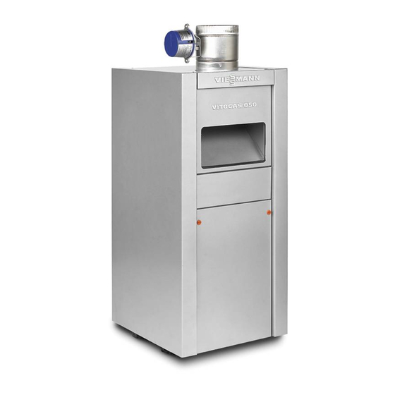
Vitogas 050, ECD Series
Gas-fired, atmospheric cast iron boiler
65 to 200 MBH / 19 to 59 kW
IMPORTANT: READ AND SAVE THESE INSTRUCTIONS FOR FUTURE REFERENCE
Warning: If the information in this manual is not
followed exactly, a fire or explosion may result
causing property damage, personal injury or
loss of life.
Do not store or use gasoline or other flammable liquids
in the vicinity of this or any other appliance.
WHAT TO DO IF YOU SMELL GAS
Do not try to light any appliances.
Do not touch any electrical switches, do not use any
phone in your building.
Immediately call your gas supplier from a neighbor's
phone. Follow the gas supplier's instructions.
If you cannot reach your gas supplier, call the fire
department.
Installation and service must be performed by a
qualified installer, service agency or the gas supplier.
WARNING
Should overheating occur or the gas supply fail to shut
off, do not disconnect the electrical supply to the
pump. Instead, shut off the gas supply at a location
external to the appliance.
5167 445 v1.1 03/2007
Contents:
Technical Data ..........................................................................3
Boiler handling - location..........................................................3
Flushing of existing piping ........................................................4
Vent damper installation ...........................................................4
Closet installation......................................................................5
Combustion air supply ..............................................................6
Installation on combustible floor ...............................................8
Boiler water piping ....................................................................8
Honeywell adjustable high limit aquastat ..................................9
Circulating pump .......................................................................9
Initial system fill.......................................................................10
Boiler venting ..........................................................................11
Gas piping...............................................................................12
Gas pressure - orifice sizes ...................................................12
Main burner.............................................................................13
Blocked vent and flame roll-out switch ...................................14
Wiring......................................................................................14
Electronic thermostat ..............................................................15
System start-up.......................................................................15
Maintenance ...........................................................................15
Troubleshooting ......................................................................17
Lighting instructions ................................................................18
Wiring diagrams ................................................................19, 20
Parts list ................................................................21, 22, 23, 24
Maintenance record ................................................................25
Page:
Advertisement
Table of Contents

Related Manuals for Viessmann Vitogas 050 ECD Series


Summary of Contents for Viessmann Vitogas 050 ECD Series
-
Page 1: Table Of Contents
Installation / Service Manual for use by heating contractor Vitogas 050, ECD Series Gas-fired, atmospheric cast iron boiler 65 to 200 MBH / 19 to 59 kW IMPORTANT: READ AND SAVE THESE INSTRUCTIONS FOR FUTURE REFERENCE Contents: Page: Warning: If the information in this manual is not Technical Data ................3 followed exactly, a fire or explosion may result Boiler handling –... - Page 2 This “Attention” symbol is located beside all Warning: important safety recommendations. Please follow the instructions in detail to avoid property damage, Before each heating season begins, have the following severe personal injury, or loss of life. service and maintenance done by a professional service technician: Boiler heat exchanger inspected and cleaned.
-
Page 3: Technical Data
Vitogas 050, ECD Series Technical Data Cut-away view Left view Front view (left side) Vent connection Draft hood Boiler supply water 1 ⁄ ˝ (water flows out) Boiler well for capillaries 120V power in Transformer 120V 4A max. Ignition control output to pump 24V thermostat 24V gas valve... -
Page 4: Flushing Of Existing Piping
194°F. An alternate construction is available for operation close to the boiler as possible. between 194°F and 248°F. Consult a Viessmann representative for alternate construction before ordering boiler. The vent damper must be field installed on the boiler. Read the vent damper manufacturer’s instructions before installing the... -
Page 5: Closet Installation
There are no serviceable parts on the vent damper. Defective vent dampers must be replaced. Dim “A” ECD-65, -80 47.75˝ ECD-100, -115 48.25˝ If the side wall vent system is used, the vent damper must ECD-140, -155 48.75˝ Molex not be installed. Refer to separate side wall vent system ECD-180, -200 52.75˝... -
Page 6: Combustion Air Supply
ATTENTION (latest edition) or applicable provisions of the local codes. In Follow local regulations with respect to CO detectors. Follow Canada follow CAN/CSA-B149.1 or .2 Natural Gas Installation all safety information from LP or gas supplier. Codes (latest edition) for combustion and ventilation air requirements. - Page 7 Viessmann recommends above items 1-8 for all If windows or doors are used for combustion air openings, installations, even in buildings without airtight construction.
-
Page 8: Installation On Combustible Floor
The boiler location must never be under negative pressure. 6˝ Exhaust fans, attic fans, or dryer fans may cause air to be 6˝ exhausted at a rate higher than air can enter the structure for safe combustion. Warning: Never cover the boiler or store debris or other materials near the boiler, or in any way block the flow of adequate fresh air to the boiler. -
Page 9: Honeywell Adjustable High Limit Aquastat
Thermostat without an oxygen diffusion barrier. Such systems must have connections the non-oxygen diffusion barrier tubing separated from the boiler with a heat exchanger. Viessmann recommends the use 120V pump of underfloor plastic tubing with an oxygen diffusion barrier. over 4A... -
Page 10: Initial System Fill
Low water cut-off If the ECD boiler is installed above radiation level then a low water cut-off device must be installed. See Fig. 5b for location Heating/ Cooling unit of low water cut-off device. Note: Flow direction must be as shown in Fig. -
Page 11: Boiler Venting
Boiler venting (Category I) Removal of existing boiler The mounted boiler draft hood must not be altered or modified When an existing boiler is removed from a common venting in the field. system, the common venting is likely to be too large for proper venting of the appliances remaining connected to it. -
Page 12: Gas Piping
The gas ignition system and components must be protected from water (dripping, spraying, rain etc.) during appliance operation and service (circulator replacement, control Manual gas replacement, etc.). If boiler has been underwater, all electrical shut-off valve parts must be replaced. Ground Pressure relief valve joint union... -
Page 13: Main Burner
Manifold orifices – natural gas (1,000 Btu/cu. ft.) Main burner (see Fig. 8) Proper flame: Upper main flame cone with light orange Boiler Orifices Low Altitude High Altitude Gas valve/manifold coloring, sharply defined individual flames size required 0-610m 610-1370m pressure (Fig. -
Page 14: Blocked Vent And Flame Roll-Out Switch
Left Right Left Right Fig. 9e ECD-(180, 200) pilot location Fig. 9b ECD-(65, 80) pilot location Blocked vent and flame roll-out switches Flame Roll-Out Switch Blocked Vent Switch Model 60T14 (140°F) Model 60T14 (235°F) Left Right Note: Fig. 9f shows pilot burner flame with proper flame adjustment. Boiler wiring Refer to wiring diagrams on pages 19, 20. -
Page 15: Electronic Thermostat
WR 8A02A-8 Isolation transformer relay See wiring diagram in rear of manual and wiring label on boiler. Viessmann reserves the right to substitute electrical components as necessary. The boiler wiring label takes precedence. Caution To boiler thermostat Label all wires prior to disconnection when servicing controls. - Page 16 Boiler servicing – heat exchanger cleaning Diagonal brush application A service/inspection of the boiler and the system is mandatory once a year. Before heating season starts, boiler/burner should be serviced by a qualified service agency. The owner should establish a service contract with a qualified service agency.
-
Page 17: Troubleshooting
VR8204P1049 VR8304P3308 (ECD-200) Ignition Control S8600H1006 S8600H1006 Pilot Burner * Q3451A2012 Q3451A2012 Pilot Orifice .018 inches dia. .014 inches dia. 390686-4 390696-24 BCR 18 BBR 14 Pilot burner has ignition cable permanently attached. Consult your Viessmann representative for parts replacement. -
Page 18: Lighting Instructions
Lighting Instructions for Intermittent Pilot (Spark to Pilot) FOR YOUR SAFETY READ BEFORE OPERATING WARNING: If you do not follow these instructions exactly, a fire or explosion may result causing property damage, personal injury or loss of life. A. This appliance is equipped with an ignition device If you cannot reach your gas supplier, call the fire which automatically lights the pilot. -
Page 19: Wiring Diagrams
S3 T2 T1 T1 T2 S3 S3 T2 T1 T1 T2 S3 Fig. 12... - Page 20 Vitogas 050, ECD Series with Honeywell intermittent pilot and vent damper – Ladder diagram 120V, 60Hz, less than 12A – Field supplied See Fig. 4a. for wiring pumps over 4A Pump Use isolation relay for 120V, 4A Max. pumps over 4A 120V See Fig.
- Page 21 Vitogas 050, ECD Series Cast Iron Atmospheric Gas-Fired (exploded view example of ECD-140 / ECD-155) Inspection opening for heat exchanger 29,30 Fig. 13 Note: Ref. No. 19 not shown, as only applicable to ECD-180 / ECD-200. Note: Ref. No. 35 is at a different location for the ECD-180 / ECD-200.
- Page 22 Part No. Name of Part Silver Orange -100 -115 -140 -155 -180 -200 9544 200 9543 897 Left panel 9544 201 9544 189 Right panel 9544 202 9543 893 9544 203 9543 892 Back panel 9544 204 9543 909 9544 205 9543 910 9544 206 9543 911 9544 207 9543 913 9544 208 9543 918...
- Page 23 Part No. Name of Part Silver Orange -100 -115 -140 -155 -180 -200 16 Section – right side* 9507 593 9507 593 17 Section – left side* 9507 592 9507 592 18 Section intermediate* 9507 596 9507 596 9507 595 9507 595 19 Section int.
- Page 24 9543 729 9543 729 47 Blocked vent switch 60T15 235F (235°F) 48 3-pole 41 plug 7037 464 7037 464 Female Male 7270 385 7270 385 Replacement parts are available from your Viessmann dealer. Installation of incorrect replacement parts can cause unsafe operation.
- Page 28 Viessmann Manufacturing Company (U.S.) Inc. Viessmann Manufacturing Company Inc. 45 Access Road 750 McMurray Road • • • • Warwick, Rhode Island 02886 Waterloo, Ontario N2V 2G5 Canada • • Tel. (401) 732-0667 Fax (401) 732-0590 Tel. (519) 885-6300 Fax (519) 885-0887 •...
Need help?
Do you have a question about the Vitogas 050 ECD Series and is the answer not in the manual?
Questions and answers