
Subscribe to Our Youtube Channel
Related Manuals for Simplex POWERSTAR 110 KW


Summary of Contents for Simplex POWERSTAR 110 KW
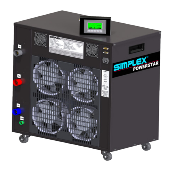
- Page 1 Document Number: DOC-00668 110 KW POWERSTAR 125 KW NORTHSTAR 150 KW NORTHSTAR DIGITAL LOAD BANK...
-
Page 3: Table Of Contents
Table of Contents Warnings and Cautions ..................4 Nameplates and Placards .................. 6 1. Introduction ......................... 6 2. Instruction Placards ......................6 III. Description and Specification ................11 1. Introduction ........................11 2. Overview of Use ........................ 11 3. Capabilities ........................11 4. - Page 4 Table of Figures Warnings and Cautions ..................4 Nameplates and Placards .................. 6 III. Description and Specification ................11 Unpacking ......................13 Installation ......................14 1. Airflow Diagram ........................ 14 Operating Instructions ..................16 1. Screen Explanation ......................16 2. Screen Explanation 2 ....................... 16 3.
- Page 5 Last Revision Date: March 15, 2016 For the most up-to-date information for this product and others, please contact Simplex, Inc. at 1-800-637-8603 or visit us on the web at http://www.simplexdirect.com.
-
Page 6: Warnings And Cautions
1.0 WARNINGS AND CAUTIONS Four commonly used safety symbols accompany the DANGER, WARNING, and CAUTION blocks. The type of information each indicates is as follows: This General warning symbol points out important safety information that, if not followed, could endanger personal safety and/or property of others. - Page 7 • Before installing or servicing this (and related) equipment, make sure that all power voltage supplies are completely turned off at their source. Failure to do so will result in hazardous and possibly fatal electrical shock. • In case of accident caused by electric shock, immediately shut down the source of electrical power.
-
Page 8: Nameplates And Placards
2.0 NAMEPLATES AND PLACARDS 2.1 Introduction This section will provide copies of the nameplates and placards for this Load Bank in the event that the current nameplates and placards become unreadable. 2.2 Instruction Placards... -
Page 13: Description And Specification
3.0 DESCRIPTION AND SPECIFICATION 3.1 Introduction This section will provide a brief synopsis of the use of the load bank. Simplex, Inc. reserves the right to change this synopsis, and this section should only serve as a brief concept of the device. -
Page 14: Safety
3.4 Safety In the interest of safety, the load bank is equipped with an automatic system to de- energize all the load if conditions are met that may be dangerous to the operator or could damage the hardware. If the load elements aren’t cooled properly due to a fan failure or high exhaust temperature, the load bank will de-energize any applied load. -
Page 15: Unpacking
4. Examine all accessible internal electrical components such as fuses, contactors, and relays. Check lugged wires at these components. 5. Visually inspect element chamber for foreign objects, broken ceramic insulators, and mechanical damage. If any problems are observed during Primary Inspection, call the Simplex Service Manager at 1-800-637-8603. -
Page 16: Installation
5.0 INSTALLATION 5.1 Introduction With a portable load bank, placement is not a permanent thing; however, because of its mobile nature, extra attention is required whenever the load bank is moved. Whenever the load bank is moved, even within the same room, the following warnings must be observed. - Page 17 CAUTION This load bank is high-powered, technical, industrial equipment operating at dangerous voltages, and temperatures. It is capable of damage to itself or property or personnel, if improperly used. It is not a consumer product. It must be installed, connected, and operated by personnel properly trained and experienced in its use.
-
Page 18: Operating Instructions
6.0 OPERATING INSTRUCTIONS 6.1 Introduction The load bank was designed with simplicity in mind. The hardware is simple to use and easy to maintain. Using a hand-held interface, the load bank can apply a desired load to a target device. In this section, you will find: —... - Page 19 Reference Explanation Number The “Fan” switch will turn the fan and unit on. The “Load” switch will apply the set load to the testing source. The “Vavg” is the average voltage of the load. This section will designate the phase in which the load bank is running. It can be in 1Ph (single phase) or 3Ph (3-phase).
-
Page 20: Handling
6.3 Handling 6.3.1 General Handling Information When moving the Load Bank, please keep the device upright and do not transport on its side. Use the attached rollers for short distances. If the unit needs to be lifted, only lift the unit using the handles on the sides or lifting the from the bottom of the unit. -
Page 21: Power On
6.4.2 Operation Maintenance 1. Visually observe correct fan operation and investigate any unusual fan-related noises. 2. Check air intake for obstructions and confirm positive air flow. 3. Verify the “Normal” indicator is shown before proceeding. 6.4.3 Applying a Load 1. The HMI will display “XXXKW Available” in the “Available” section. This number represents the amount of load available. -
Page 22: Shutdown
6.5 Shutdown 1. To shut down the Load Bank, de-energize the load by switching the “Load” switch to “Off.” 2. Select the “Fan” switch to “Off.” The unit will begin a cooldown phase for a set duration. If desired, the cooldown timer can be set to zero. 3. -
Page 23: Error Menu
Selecting “MAN” will load the manual selection screen. This menu allows for selection of indi- vidual steps for testing purposes. Selecting “MDL” will load the model screen. This screen is for Simplex usage only. Table 3 Setup Screen Definitions After setting these various options, the HMI controller is ready for your customize use. -
Page 24: Auto Jog Chart
To access the Auto Jog function, you must press “SHF” (F5) and then select “AJG” (F2) from this alternate menu (See Figure 11). See Figure 12 for an example of how to set up an auto jog operation. Figure 11 Auto Jog Selection Figure 12 Setting Auto Jog To set up an Auto Jog operation: 1. -
Page 25: Alarms And Warnings
7.0 ALARMS AND WARNINGS 7.1 Introduction With Simplex Portable Load Banks, there are few things that will cause a serious issue. One of the primary alarms that will occur is an over-temperature alarm. In this section, you will learn: — What triggers an alarm. -
Page 26: Supplemental Equipment
In order apply load to the load bank from a power source, you will need to connect via Cam-Lok cables. The required type is 15 series, single-pole detachable plug. The communications cable and 120V power cable are included. Description Simplex Numbers Vendor Reference Black Female Plug 25608823... -
Page 27: Diagnostics And Troubleshooting
9.0 DIAGNOSTICS AND TROUBLESHOOTING 9.1 Introduction Through good practice, cumulative issues can be prevented through basic maintenance. In the unlikely event that something goes wrong with the load bank, we will cover how to solve some of the more common problems. Finally, if the need arises, we will cover how to replace various parts for the load bank. -
Page 28: Failure Subsystem
9.3 Failure Subsystem Excessive intake/exhaust temperatures, any reduction in cooling air flow, or a Loss of Communication from either the hand-held controller or the controlling load bank is indicated by the illumination of the “Error” indicator on the WARNING hand-held remote control. Any of the above conditions will result in the load bank If a failure occurs during Load Bank opera-... -
Page 29: Parts Breakdown
9.4 Parts Breakdown Figure 15 Fan View Figure 16 Exhaust View Figure 17 Side View Reference Description Load Connection AØ Load Connection BØ Load Connection CØ Ground Connection Product Info Communication Ports Control Power 120VAC Intake Exhaust Lift Handle Product Label Table 6 Parts of a Load Bank... - Page 30 Did You Know? Simplex was founded in 1938 in Burlington, Iowa by Michael Debrey, a Hungarian immigrant. A self-taught inventor, Debrey introduced multiple innovations to the electrical engineering field, including the Automatic Voltage Regulator. Simplex was moved to East Moline, Illinois, where it remained until 1951,...
-
Page 31: Ordering Information
Portable Load Bank. The options below are for the standard models. For any custom orders or for any clarification or questions on the items, please contact your Simplex Inc. representative. When ordering, please attach your purchase order to this form and fax it to Simplex, Inc. - Page 32 Did You Know? Load banks simulate the “real world” loads that the power source will experience. Electrical load can be broadly classified as resistive, magnetic, and capacitive. In the real world, these components are mixed, as they are with a load bank, except with the load bank, full control of the components is possible.
-
Page 33: Appendix A - Abbreviations In This Manual
APPENDIX A — ABBREVIATIONS IN THIS MANUAL Listed below are abbreviations of terms found for the Portable Load Bank. When following a drawing, utilize this guide to define abbreviated system and component names. As this is a master list, drawings and text pertaining to your equipment may not contain all these terms. A - Amps AC - Alternating Current GND - Ground... -
Page 34: Appendix B - Important Formula
APPENDIX B — IMPORTANT FORMULA OHMS LAW: OHMS = VOLTS / AMPS ( R = E / I) AMPS = VOLTS / OHMS (I = E / R) VOLTS = AMPS / OHMS (E = IR) 3 Phase Resistance = (V² X 2) / W Amperage = W / (V X 1.732) 208V RES 86.5 17.3 8.6... - Page 35 Simplex, Inc. 2100 Boggs Road 5300 Rising Moon Road Springfield, IL 62711-6228 Duluth, GA 30096-4691 1-800-637-8603 http://www.simplexdirect.com...
Need help?
Do you have a question about the POWERSTAR 110 KW and is the answer not in the manual?
Questions and answers