
Related Manuals for CESVA DC112k


Summary of Contents for CESVA DC112k
- Page 1 DC112k / DC112a Dosimeter / Dosimeter Spectrum Analyser User’s Manual M_DC112kDC112a_v0009_20170113_EN...
-
Page 3: Table Of Contents
User’s manual ENGLISH 1. GENERAL DESCRIPTION ....................3 1.1 Activation of the frequency analysis in octaves module for the DC112k ....... 4 1.2 Main Characteristics of the DC112k/DC112a ............... 4 1.3 Functions ........................5 1.4 Description of the DC112k/DC112a ................6 1.5 Screen .......................... - Page 4 3.3 Viewing the register .....................27 3.4 Erasing the memory ....................27 4. DATA TRANSFER ......................28 4.1 Transfer of data to a PC: Communication software .............28 5. PRECAUTIONS AND WARNINGS ..................29 6. TECHNICAL SPECIFICATIONS ..................30 6.1 Measurement range ....................30 6.2 Peak detector - L function ..................30 peak 6.3 Frequency weighting ....................30...
-
Page 5: General Description
The DC112k/DC112a is the ideal instrument for measuring noise in places where it can reach harmful levels. The DC112k can be converted into a DC112a, for which it is necessary to acquire the module EF112a, either when purchasing the DC112a, or subsequently. To acquire it, simply contact your official CESVA distributor, give them the serial number of your SLM and place an order for the module. -
Page 6: Activation Of The Frequency Analysis In Octaves Module For The Dc112K
The DC112k/DC112a has a USB port to download data to a PC at high speed. While the DC112k/DC112a is connected to the USB port of a PC it does not need batteries as it is powered by the USB port of the PC. -
Page 7: Functions
(Q= 3, 4, 5 and 6), threshold level (L corresponding to the integration time (T). Apart from the aforementioned functions corresponding to the measurement time, when it carries out a recording, the DC112k/DC112a saves the time history of the following functions every T period: ... -
Page 8: Description Of The Dc112K/Dc112A
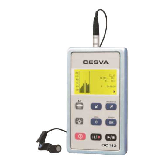
1.4 Description of the DC112k/DC112a The most important parts of the DC112k/DC112a are detailed in the following diagram. 1. Microphone Prepolarised lapel condenser microphone: P007. 2. Support clip. Adjustable clip to fix the microphone to a lapel or helmet. 3. Microphone extension cable. 1m flexible extension cable for the P007 microphone. - Page 9 DC112k/DC112 User’s manual...
-
Page 10: Screen
1.5 Screen While the DC112k/DC112a is carrying out a measurement the following information is shown in the bottom right-hand corner of the screen: Measurement time lapsed t Battery status indicator Measurement status indicator: measurement finished measurement in progress... - Page 11 Key to continue a measurement (when the DC112k/DC112a is on Key to interrupt (PAUSE) a measurement (while the DC112k/DC112a is on Or to begin a recording in the memory (when the DC112k/DC112a is on Key to return to the previous octave band Key to move on to the next octave band, or to move on to the numerical screen with projected parameters.
-
Page 12: Using The Dc112K/Dc112A
If any of these elements should be missing, contact your official distributor. 2.1.2 DC112k/DC112a Power source The first operation to carry out, before switching on the DC112k/DC112a, is to supply power. The DC112k/DC112a dosimeter is powered by a 6LF22 type 9V alkaline battery, or via the USB port [8]. -
Page 13: Connection And Disconnection Of The Microphone
We recommend that you always carry new replacement batteries 2.1.3 Connection and disconnection of the microphone Before connecting or disconnecting the P007 microphone of the DC112k/DC112a dosimeter, make sure the DC112k/DC112a is switched off. To connect the microphone to the dosimeter, hold the male plug of the microphone [4] in the middle. -
Page 14: Fixing The Dc112K/Dc112A On The User (Worker)
2.1.4 Fixing the DC112k/DC112a on the user (worker) The DC112k/DC112a has a support clip [13] to fix it to the user’s belt (see figure) and an adjustable metal clip [2] to attach the microphone to their collar or helmet. Any excess wire should be wound in a figure 8. - Page 15 DC112k/DC112 User’s manual Numerical screen with L Projected parameters numerical screen ’ Numerical screen with L (only OSHA, MSHA and CUSTOM) Projected parameters ’ numerical screen, with L (only OSHA, MSHA y CUSTOM) 1/1 Spectrum analyser screen (only DC112a) Time history screen...
-
Page 16: Testing The Dc112K/Dc112A
CB004 or CB006 sound calibrator and proceed as follows: 1) Insert the microphone of the DC112k/DC112a in the cavity of the calibrator. Make sure it has been fully inserted, and is parallel to the axis of the calibrator (see figure). -
Page 17: Measuring With The Dc112K/Dc112A
DC112k/DC112a. 4) Access the option SETTINGS SENSITIVITY ADJUST. 5) The sound pressure level measured by the DC112k/DC112a will appear on the screen, along with the time and date of the last time the sensitivity was modified. -
Page 18: Prior Adjustments
Projection time (t ), predicted noise exposure time Integration time (T). Average time used for the measurement of average sound pressure level. The DC112k/DC112a saves the time history for the parameters (L or L Cpeak Zpeak ’ and L ). - Page 19 DC112k/DC112 User’s manual 2.- PERSONALISED SETTING Choose the CUSTOM option by pressing and press A new screen will appear: The parameters that appear on this screen can be set to the needs of the user. These parameters are: Criterion level (L...
-
Page 20: Beginning A Measurement
2.3.3 Function display The DC112k/DC112a measures all functions simultaneously. Described below are the different ways of displaying the acoustic functions for the assessment of noise in the workplace while measurement is taking place. If you change the kind of display (screen) or the octave band selected (spectrum analyser screen), measurement will continue uninterrupted. - Page 21 DC112k/DC112 User’s manual Numerical screen This screen shows, in real time, the following information: Time weighted average (8hr) (TWA) Noise dose (D) with respect to the criterion level (L Average sound level (L ) with A or C frequency weighting, F or S time weighting,...
- Page 22 ’ (only OSHA, MSHA and CUSTOM) press To display the parameters with L ’ level. The parameters displayed are calculated from values measured over the L ’ (TWA’). Time weighted average (8h) with L ’ (D’) with respect to the criterion level (L Noise dose with L ...
-
Page 23: Blocking The Keypad
Measurement time (t) integration time elapsed and integration time. 2.3.4 Blocking the keypad While a measurement or recording is in progress, the keypad of the DC112k/DC112a can be blocked; this way accidental interventions in the process can be avoided. To block the keypad, press . -
Page 24: Interrupting The Measurement
The measurement status indicator will change from 2.3.7 Consulting measured data While the DC112k/DC112a is not measuring ( ), you may consult all the functions measured. To consult them, apply the same procedure as described in section 0 on viewing data while measurement is in progress. -
Page 25: Menu Of The Dc112K/Dc112A: Register Management And Settings
The DC112k/DC112a comes with an initial configuration which makes it possible to carry out measurements without having to reset it in advance. 2.5.1 Menu access To access the DC112k/DC112a menu, make sure that no measurement is in progress ( ) and press The following screen will appear: This menu shows the main settings screen along with the time and date of the DC112k/DC112a’s clock. -
Page 26: Register Management
SAVING RESULTS: When this option is selected the DC112k/DC112a records in its memory the final results of all the functions measured. The DC112k/DC112a indicates the number of the register in which the registers have been recorded. For more information see section 3.4. -
Page 27: Registering Data
User’s manual 3. REGISTERING DATA The DC112k/DC112a can record in the internal memory the values of the functions measured. When the equipment is switched off the recorded data is not lost and can be retrieved and displayed directly from the DC112k/DC112a or transmitted to a PC. The memory can be erased directly from the DC112k/DC112a. - Page 28 During the recording process the recording icon ( ) will appear on the screen. The DC112k/DC112a saves the following values once each integration period (T) has finished: ...
-
Page 29: Continuing A Recording After The Dc112K/Dc112A Has Been Switched Off
To continue the measurement, see section 3.2.1. If the power source of the DC112k/DC112a is cut off suddenly during a recording, (removal of the battery, or the USB connection), the recording will be incomplete. It will not be able to be viewed with the DC112k/DC112a;... -
Page 30: Data Transfer
Register management (erasing, etc.). Programming the dosimeter (time, parameters, etc.). To carry out these functions the DC112k/DC112a must be connected to the USB port of a computer with the cable supplied. For more information about Capture Studio, use the help that it incorporates. -
Page 31: Precautions And Warnings
The microphone must never be dismantled, as this may cause permanent damage. Any knocks on the DC112k/DC112a will be picked up by the microphone, and this may affect the value of the measurement. We recommend that you test the DC112k/DC112a before and after every measurement, using the sound calibrator. -
Page 32: Technical Specifications
6. TECHNICAL SPECIFICATIONS 6.1 Measurement range Measurement range Function Lower limit Upper limit Units 0000:00:00 1999:59:59 HHHH:MM:SS 9999999 Cpeak DOSE 9999999 999,9 Total Maximum Noise at 20 ºC Frequency Weighting Total Maximum Noise 43 dB 53 dB Margin of frequencies maintained when the frequency response 31,5 Hz a 12,5 Khz extends to frequencies below 63 Hz or above 8 kHz 6.2 Peak detector - L... -
Page 33: Parameters
DC112k/DC112 User’s manual The following table shows the A and C frequency weightings along with their tolerance. Frequency A Weighting C Weighting Tolerance (Hz) (dB) (dB) (dB) 2,0 - 26,2 - 0,8 1,5 - 16,1 - 0,2 1,5... -
Page 34: Octave Band Filters
Typical values for C weighting frequency Frequency Maximum level Minimum level (Hz) (dB) (dB) 139,2 139,8 140,0 140,0 1,000 140,0 2,000 139,8 4,000 139,2 8,000 137,0 6.6 Octave band filters Frequency evaluation system Base 10 Reference attenuation Margin of frequencies for real time operation 31,5 Hz a 16 kHz Octave band central frequencies Nominal central frequency... -
Page 35: Microphone
DC112k/DC112 User’s manual 6.7 Microphone P007 Prepolarised ½” condenser microphone with preamplifier incorporated Nominal sensitivity (typical) 11,2 mV/Pa Length of cable Correction of sound field generated by a B&K model 4226 multifunction acoustic calibrator to diffuse field Frequency (Hz) Correction (dB) -
Page 36: Single Pole Pulse Response
6.10 Single pole pulse response Typical E deviation with positive and negative pulses 6.11 Warm-up time Warm-up time 30 seconds 6.12 Influence of temperature Operation range 0 a +40 °C Storage without batteries -20 a +60 °C 6.13 Influence of humidity Operation range: 30 to 90 % Storage without batteries:... -
Page 37: Electromagnetic Compatibility
The equipment shows no degradation or loss of function after being exposed to electrostatic discharges. The DC112k/DC112a shows a slight variation with respect to the electric field with the instrument perpendicular to the propagation direction and the cables extended perpendicular to the main axis of the instrument... -
Page 38: Dimensions And Weight
It is recommended that the DC112k/DC112a be sent to an authorised laboratory for calibration every two years, and to test its acoustic and electric characteristics are working correctly. -
Page 39: Accessories
DC112k/DC112 User’s manual 6.21 Accessories Standard accessories FNS012 Case SFT030 Computer programme CN1US Connection cable 9 volt battery Optional accessories CB004 Class 2 acoustic calibrator TR-40 Tripod: Max height 1,2 m TR050 Tripod: Max height 1,5 m ML040 Carrying case (48x37x16 cm) -
Page 40: Appendix A: Functions
7. Appendix A: Functions 7.1 Definition of functions 7.1.1 Average sound level Average level of the sound pressure measured with a particular time weighting, exchange rate and frequency weighting. 7.1.2 Time weighted average (8h) Average level of L which, maintained constant for a particular length of time (8 horas), has the same energy as the event measured. -
Page 41: Continuous Equivalent Sound Pressure Level
The equivalent level (L ) is the equivalent level corresponding to T integration time (a programmable parameter). It is displayed every T time period. In other words, every T time period the DC112k/DC112a shows the equivalent level of the last T time period. - Page 44 Maracaibo, 6, – 08030 BARCELONA (ESPAÑA) Tel. (+34) 934 335 240 – FAX (+34) 933 479 310 info@cesva.com e-mail: www.cesva.com...
Need help?
Do you have a question about the DC112k and is the answer not in the manual?
Questions and answers