
Related Manuals for doble TDR900


Summary of Contents for doble TDR900
- Page 1 Doble TDR900 User Guide Doble Engineering Company 85 Walnut Street Watertown, Massachusetts 02272-9107 (USA) Telephone: (617) 926-4900 Fax: (617) 926-0528 www.doble.com PN 500-0652 72A-2612-01 Rev. A 09/06...
- Page 2 Doble Engineering Company. Doble and the Doble logo are registered in the U.S. Patent and Trademark Office and are trademarks of the Doble Engineering Company. ®...
- Page 3 Doble TDR900 User Guide FOR ANY DAMAGES, INCLUDING WITHOUT LIMITATION, PERSONAL INJURY OR PROPERTY DAMAGE CAUSED BY THE USE OR APPLICATION OF THE INFORMATION CONTAINED HEREIN, ANY INCIDENTAL OR CONSEQUENTIAL DAMAGES, EXPENSES, LOST PROFITS, LOST SAVINGS, OR OTHER DAMAGES ARISING OUT OF THE USE OF OR INABILITY TO USE THIS INFORMATION SUCCESSFULLY.
- Page 4 Doble TDR900 User Guide This page intentionally left blank. 72A-2612-01 Rev. A 09/06...
- Page 5 Doble TDR900 User Guide PREFACE This User Guide describes how to use Doble Engineering’s T-Doble Software. The purpose of this guide is to assist with application of the T-Doble software in testing current breaking devices, such as Circuit Breakers. Notes, Cautions and Warnings Note, Caution and Warning icons denote information of special interest.
- Page 6 Doble TDR900 User Guide This page intentionally left blank. 72A-2612-01 Rev. A 09/06...
-
Page 7: Table Of Contents
Doble TDR900 User Guide Table of Contents Chapter 1 Introduction to the TDR900.................1 Aims of this Guide.....................1 Timing Tests with the TDR900 .................1 Terminology ......................1 Safety First.........................2 Chapter 2 Parts List – Hardware and Software .................3 Instrument Overview ....................3 Front Panel Connections....................5 Basic Cables and Accessories..................5... - Page 8 General Set Up Information ..................19 Preparing the Breaker – Off-Line Tests ..............19 Preparing the Breaker – On-Line Tests ..............20 Preparing the Doble TDR900 Instrument and PC ...........20 Connect Test Leads to Breaker................21 5.5.1 Overall Test (Dead Tank or OCB test) ...........21 5.5.2...
- Page 9 Transferring Data between PC’s................63 6.10 Closing the Software ....................63 Chapter 7 Technical Support and Troubleshooting ..............65 PC ..........................65 Installing Software on a PC ..................65 Checking Communication between PC and TDR900 ..........65 Field Repairs......................66 Parts List ........................66 72A-2612-01 Rev. A 09/06...
- Page 10 Figure 3. Schematic of Front Panel Connections................5 Figure 4. Safety Ground........................6 Figure 5. TDR900 OCB Connection ....................7 Figure 6. TDR900 EHV Connections: two sets of three ..............7 Figure 7. TDR900 Motion Connections ..................7 Figure 8. TDR900 Analog/Event Connections................8 Figure 9.
- Page 11 Figure 53. Preferences – Plotting Sub-tab ..................58 Figure 54. Preference - Files......................59 Figure 55. Help Tab ........................59 Figure 56. “Instruments” tab to connect PC to TDR900 .............. 60 Figure 57. No TDR900 instrument found..................61 Figure 58. Instruments Tab: Connect to TDR900 ................ 62 Figure 59.
- Page 12 Doble TDR900 User Guide List of Tables Table 1. Minimum PC Requirements ..................65 Table 2. Parts List ......................... 66 72A-2612-01 Rev. A 09/06...
-
Page 13: Chapter 1 Introduction To The Tdr900
TDR900 test set. Timing Tests with the TDR900 This guide allows the user to perform timing tests with the TDR900 test set. Most users will be testing circuit breakers. However, there is no reason why the user cannot use the same test set to time circuit switches, LTC contacts or other devices. -
Page 14: Safety First
Doble TDR900 User Guide Sectional test: Sometimes called a live tank test or an EHV test. This is a test which looks at individual breaks per phase. Each individual moving second of the breaker can be timed separately. Off-line test: Off line is the usual state for a breaker to be in when performing a breaker timing test;... -
Page 15: Chapter 2 Parts List - Hardware And Software
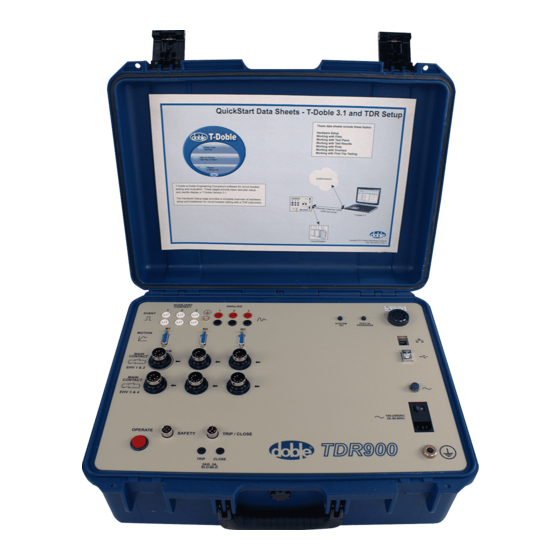
Parts List – Hardware and Software Instrument Overview The TDR900 Instrument comes complete with packaged hardware, software, and cables as shown in Figure 1. This section provides an introduction to the various parts and accessories that comprise the Doble TDR900 Instrument. -
Page 16: Figure 2. Tdr900 Instrument Front View
Doble TDR900 User Guide Figure 2. TDR900 Instrument Front View 72A-2612-01 Rev. A 09/06... -
Page 17: Front Panel Connections
Doble TDR900 User Guide Front Panel Connections Figure 3 gives a schematic view of the front panel connections on the TDR900. Figure 3. Schematic of Front Panel Connections Basic Cables and Accessories The TDR900 comes with basic cables to allow communication with the PC, safety grounding and control. -
Page 18: Safety/Chassis Ground
The TDR900 uses a 3-amp fast blow fuse as indicated on the panel and instrument label. Software Software to control the TDR900 must be run on a PC; the PC is connected to the TDR900 via a USB cable or an Ethernet cable. -
Page 19: Sectional Test Cable Option (Ehv - Live Tank)
Figure 6. TDR900 EHV Connections: two sets of three Motion Option The Motion option allows for a motion (travel) measurement on a breaker. A transducer is needed to introduce the motion measurement to the TDR900. Figure 7. TDR900 Motion Connections 72A-2612-01 Rev. A 09/06... -
Page 20: Analog/Event Cable Option
The Analog and Event Cables allow for measurements using external sensors. Event channels are also called Auxiliary channels. This is where an analog sensor, such as a clip on CT would be connected. Figure 8. TDR900 Analog/Event Connections 72A-2612-01 Rev. A 09/06... -
Page 21: Chapter 3 Safety And Personnel
Grounding The apparatus under test and the Doble TDR900 Instrument must be solidly and commonly grounded or earthed. This also applies to any mobile equipment being tested. See Figure 9 for an example of a safety ground connection. -
Page 22: Personnel Safety
Doble TDR900 User Guide Figure 9. Connecting Safety Ground to Breaker Note: Proper grounding techniques are a very important step in safety and in ensuring reliable breaker test results. Personnel Safety A pretest meeting is recommended. Other crews may be working on non-test related tasks in close proximity to equipment being tested. -
Page 23: Chapter 4
Doble TDR900 User Guide Chapter 4 Breaker Operation and Testing Theory This chapter gives some basic theory circuit for breakers in relation to their operation and testing. An ANSI definition, C37.100 states: “A breaker is a mechanical device capable of making, carrying, and breaking current... -
Page 24: How A Breaker Operates
Doble TDR900 User Guide How a Breaker Operates In an “open” operation, also called a “trip,” the breaker must: • Have conducting elements which move apart • Be extinguished when an arc develops between the contacts • Have conductors which stay far enough apart for the arc not to “restrike” which would allow current to flow again In a “close”... -
Page 25: Arc Quench And Insulation
Doble TDR900 User Guide 4.4.3 Arc Quench and Insulation In all breakers there is a need, during the trip operation to extinguish any arc developed. This may be achieved through: • Air blast • Oil • SF6 • Vacuum • Some other means The act of extinguishing the arc is related to the need to insulate the conductors. -
Page 26: Breaker Example
Doble TDR900 User Guide 4.5 Breaker Example An example of an Oil Circuit Breaker is given here so as to identify salient features. Other designs may have different components and arrangements. Bushings Guide Assembly Tank Liner Lift Rod Guide Contact Assembly... -
Page 27: Why Test A Breaker
• Improper stop adjustments • Malfunctioning shock absorbers, buffers or dash pots • Synchronization of contacts and phases Pleas refer to the Doble training notes for detailed discussion of these and other breaker issues. 4.7 Why Test a Breaker? Breaker tests are performed to: •... -
Page 28: Performing An Overall Test (Ocb Or Dead Tank)
Set up for a sectional test is more complex than an overall test as test leads are needed for each break. The TDR900 can perform tests on up to four breaks per phase on three phases at one time. By using a common connection to all test leads for a single phase, up to 12 breaks per phase may be measured for each phase. -
Page 29: First Trip Tests
This can be performed using the analog channels on the TDR900. 4.10 Other Tests The TDR900 is also a data recorder and may be configured to record data under a variety of conditions and in response to given events. These can be configured using the standard software to control the input channels and record data. - Page 30 Doble TDR900 User Guide This page intentionally left blank. 72A-2612-01 Rev. A 09/06...
-
Page 31: Chapter 5 Breaker Timing Tests With T-Doble: Overview
• Do not drop or throw the TDR900. • Do not use the TDR900 or any transducer as a step or a platform. • Do not expose the TDR900 to rain, snow, sand, excessive heat or dust. -
Page 32: Preparing The Breaker - On-Line Tests
“System OK” LED will come on to indicate status as “OK.” The T-Doble software should be run on the user PC. Make sure the T-Doble software is installed on the PC hard drive, not a network drive. -
Page 33: Connect Test Leads To Breaker
Doble TDR900 User Guide Connect Test Leads to Breaker Connect the safety ground to the breaker and to the Doble TDR900 test set. Caution: No contact test leads (Sectional EHV or Overall OCB) should be attached to the breaker if it is still on load or energized. -
Page 34: Sectional Test (Live Tank Or Ehv Test)
Doble TDR900 User Guide Connect the Common (black color-coded) lead to the bushings which have been grounded; connect the three-phase leads (color-coded red, yellow and blue) to the three ungrounded breaker bushings (one to each). TDR900 & PC Figure 12. Contact Monitor Cable for Overall Test 5.5.2 Sectional Test (live Tank or EHV test) -
Page 35: Install Motion Transducer
Figure 14. 2) Remove the circuit breaker top cap. 3) Install the transducer mounting platform – this is not supplied with the TDR900; the transducer may be secured directly to the tank. 4) Insert the Transducer Connecting Rod into the threaded hole in the circuit breaker operating (lift) rod. -
Page 36: Perform A Test
• Has the external ground cable (safety ground or chassis ground) been installed on the TDR900 and connected to the breaker ground? • Is proper AC power available for the TDR900? • Has one end of each phase of the breaker been grounded? •... -
Page 37: Running A Test
Results tab. It will automatically be saved. Powering Down the Doble TDR900 Instrument Power down the TDR900 using the power switch. Closing the T-Doble Software The software automatically saves data. Close the software using standard Windows ™... - Page 38 Doble TDR900 User Guide This page intentionally left blank. 72A-2612-01 Rev. A 09/06...
-
Page 39: Chapter 6 T-Doble Software Details
When testing in the field using a TDR900, the PC where the software is installed should not be connected to any other network and should not have a wireless network enabled (or switched on). -
Page 40: Dealing With Data: Test Plans And Test Results
The software then opens at the “Files” screen, see Figure 17. Figure 17. T-Doble Initial Screen: Files Dealing with Data: Test Plans and Test Results There are three distinct but closely related types of data handled by the T-Doble software: • A library test plan • A breaker test plan •... -
Page 41: Software Organization
There may be many results files for any particular breaker. Software Organization The T-Doble software is controlled through tabs. Each of the main tabs at the top of the screen (for example, the “Files” tab shown in Figure 17), has sub-tabs which are appropriate to it. -
Page 42: Figure 18. Test Results Legend
Doble TDR900 User Guide Figure 18. Test Results Legend It is possible to overlay similar signals on the same chart by dragging and dropping their legend entry. Similarly, it is possible to change the order of signals displayed by dragging and dropping legend entries. -
Page 43: Buttons
Doble TDR900 User Guide Figure 19. Using the Legend to Manage Traces 6.5.2 Buttons There are several buttons which appear while using the software – they are in the top right corner beneath the main tab bar. 6.5.2.1. “New Plan” Button This button takes the user to a blank breaker nameplate tab. -
Page 44: Software Main Tabs And Sub-Tabs
Doble TDR900 User Guide 6.5.2.4. “E-Mail” Button The “E-Mail” button allows selection of multiple tests for e-mail. 6.5.2.5. “Save” Button The “Save” button saves the data. If a file was imported from TRX, it will be saved in an XML format. The original file will be unchanged. -
Page 45: Figure 20. Browse Files
Doble TDR900 User Guide Figure 20. Browse Files Select a file to view by clicking on its entry in the table and then click one of the “Open” or “Overlay” buttons or double click on the file entry to open the file. -
Page 46: Figure 21. Sorting Files By Manufacturer
Doble TDR900 User Guide Figure 21. Sorting Files by Manufacturer The “Recently Opened Files” tab shows files which have been opened on the PC where the software is running. This list, as shown in Figure 22, is in the order files were opened and is not sortable. -
Page 47: Breaker
Doble TDR900 User Guide 6.6.2 Breaker The “Breaker” tab, as shown in Figure 23, gives information about the breaker file just opened. In a new test plan, the field entries will be blank. Figure 23. Breaker Tab - Nameplate Sub-Tab There are four sub-tabs: •... -
Page 48: Figure 24. Breaker - Timing Limits Sub-Tab
Doble TDR900 User Guide Figure 24. Breaker – Timing Limits Sub-tab 6.6.2.3. Travel Limits The “Travel Limits” tab, as shown in Figure 25, allows entry of specific timing values for a breaker. Figure 25. Breaker – Travel Limits Sub-tab 72A-2612-01 Rev. A 09/06... -
Page 49: Test Plan
Doble TDR900 User Guide 6.6.2.4. Velocity Limits The “Velocity Limits” tab, as shown in Figure 26, allows entry of generic velocity limits for a library test plan or breaker specific velocity limits for a breaker test plan. Figure 26. Breaker – Velocity Limits Sub-tab 6.6.3 Test Plan... -
Page 50: Figure 27. Test Plan - Test Setup Sub-Tab
Doble TDR900 User Guide • Sequencing • Recording Time • Sample Time • Pre-trigger Duration • Bounce Discrimination • Bounce Reporting Figure 27. Test Plan – Test Setup Sub-tab 6.6.3.2. Main Contact Channels The default “Main Contact” channels tab, Figure 28, allows for selection of either EHV or OCB type of measurements. -
Page 51: Figure 28. Test Plan -Main Contact Channels Sub-Tab - Default
Doble TDR900 User Guide Figure 28. Test Plan –Main Contact Channels Sub-tab – Default If an overall test (OCB test) type of measurement is required, check the phases to be measured. This disables the sectional (EHV) test options, as shown in Figure 29. -
Page 52: Figure 30. Test Plan -Main Contact Channels Sub-Tab - Ehv Selected
Doble TDR900 User Guide Figure 30. Test Plan –Main Contact Channels Sub-tab – EHV Selected 6.6.3.3. Other Channels The TDR900 comes complete with: • 3 Motion channels • 3 Analog inputs • 3 Event (digital) inputs Configuring these channels is through the “Other Channels” tab, see Figure 31. -
Page 53: Figure 31. Test Plan - Other Channels Sub-Tab
Doble TDR900 User Guide Figure 31. Test Plan – Other Channels Sub-tab 6.6.3.4. Timing Event The initiation point for each timing event may be configured separately, see Figure 32. Figure 32. Test Plan – Timing Event Sub-tab 72A-2612-01 Rev. A 09/06... -
Page 54: Figure 33. Timing Event Selection
Doble TDR900 User Guide The timing event may be selected by clicking on the down arrow at the right of the timing event column. Figure 33. Timing Event Selection 72A-2612-01 Rev. A 09/06... -
Page 55: Figure 34. Test Plan - Special Tests Sub-Tab
Doble TDR900 User Guide Each entry has its own detailed range, selected by clicking on the down arrow at the right of the detail column or by entering an actual value: Trip Current Close Current Analog Auxiliary 6.6.3.5. Special Tests “Special Tests”... -
Page 56: Test Results
Doble TDR900 User Guide 6.6.3.6. Notes Test Plan Notes are entered on the “notes” sub tab, Figure 35. Notes may include: • Typed text • Screen shots • Images and pictures The “Notes” tab has a set of controls at the top of the notes area which assist with content control. -
Page 57: Figure 36. Test Results - Signals Sub-Tab
Doble TDR900 User Guide Figure 36. Test Results – Signals sub-tab There are eight sub-tabs: • Signals • Main Contacts • Resistor Contacts • Motion at Main Open-Close • Motion at Resistor Open-Close • Other Channels • Notes 6.6.4.1. Signals The “Signals”... -
Page 58: Figure 37. Test Results - Main Contacts Sub-Tab
Doble TDR900 User Guide Figure 37. Test Results – Main Contacts Sub-tab The test results are checked against specifications, if available in the breaker test plan. In the results in Figure 37, a Close measurement on an overall (OCB) test is compared with the 142.0 ms maximum specified in the test plan. -
Page 59: Figure 39. Test Results Showing "Investigate" For Close Results
Doble TDR900 User Guide In Figure 39 results for a sectional test (EHV test) are found to be out of spec for the close timing. The specification is for a close measurement to lie between 40.0 and 44.0 ms. The actual values lie at between 52.0 and 53.0 ms and each entry is marked by a warning triangle signifying that investigation is needed. -
Page 60: Figure 40. Test Results - Resistor Contacts Sub-Tab
Doble TDR900 User Guide 6.6.4.3. Resistor Contacts Resistor contact timings are reported on the “Resistor Contacts” tab, Figure 40. If limits were available from the specification, then these are used to assign “OK” or “Investigate” values. Figure 40. Test Results – Resistor Contacts Sub-tab 6.6.4.4. -
Page 61: Figure 41. Test Results - Motion Sub-Tab
Doble TDR900 User Guide Figure 41. Test Results – Motion Sub-tab 6.6.4.5. Motion at Main Open-Close “Motion at Main Open-Close” tab reports average velocity at operation, using travel distance and timing measurements for calculations, as shown in Figure 42. If a rotary transducer is used, then results are in degrees, rather than linear measure, as shown in Figure 42. -
Page 62: Figure 42. Test Results - Motion At Main Open-Close Sub-Tab
Doble TDR900 User Guide Figure 42. Test Results – Motion at Main Open-Close Sub-tab 6.6.4.6. Motion at Resistor Open-Close As with Motion at main contacts (section 6.6.4.5), the “Motion at Resistor Open-Close” tab reports on average velocity at resistor open-close times, as shown in Figure 43. If measurements are made using a rotary transducer, results are given in degrees, rather than linear measurement. -
Page 63: Figure 43. Test Results - Motion At Resistor Open-Close
Doble TDR900 User Guide Figure 43. Test Results – Motion at Resistor Open-Close 72A-2612-01 Rev. A 09/06... -
Page 64: Figure 44. Test Results - Other Channels Sub-Tab
Doble TDR900 User Guide 6.6.4.7. Other Channels – Auxiliary Channels If data is recorded on auxiliary channels, it is displayed on the “Other Channels” tab, as in Figure 44. In the case shown, the Aux channels were recorded, and the rows for each channel show what event was recorded and the duration. -
Page 65: Figure 45. Test Results - Notes Sub-Tab
Doble TDR900 User Guide 6.6.4.8. Notes The “Notes” tab, Figure 45, acts in the same way as the Test Plan “Notes” tab as described in section 6.6.3.6. Figure 45. Test Results – Notes Sub-tab 72A-2612-01 Rev. A 09/06... -
Page 66: Overlay Signals
Doble TDR900 User Guide 6.6.5 Overlay Signals The Overlay signals tab allows different results to be compared. If no signals have been added to the overlay, then a null (empty) screen, as shown in Figure 46, is displayed. Signals may be added from the “Overlay” button on the Files tab or from the “Add to Overlay”... -
Page 67: Figure 47. Overlay Tab With Single Result Added
Doble TDR900 User Guide Figure 47. Overlay Tab with Single Result Added Figure 48. Overlay Tab Legend – Check Box and Red Button 72A-2612-01 Rev. A 09/06... -
Page 68: Instruments
6.6.6 Instruments The “Instruments” tab, as shown in Figure 50 allows for connection and communication between the PC and the TDR900 Instrument. 72A-2612-01 Rev. A 09/06... -
Page 69: Reports
Doble TDR900 User Guide Figure 50. Instruments Tab 6.6.7 Reports Reports are user configured to include as much detail as necessary. Click on “To Excel” to export results and charts to an Excel file. (See Figure 51.) Figure 51. Reports Tab... -
Page 70: Preferences
Doble TDR900 User Guide 6.6.8 Preferences User preferences relate to a particular PC. (See Figures 52, 53, and 54.) Figure 52. Preferences – Display Units Sub-tab Figure 53. Preferences – Plotting Sub-tab 72A-2612-01 Rev. A 09/06... -
Page 71: Help
Doble TDR900 User Guide Figure 54. Preference - Files 6.6.9 Help This is a work in progress, as shown in Figure 55. Figure 55. Help Tab 72A-2612-01 Rev. A 09/06... -
Page 72: Connect To A Tdr900 Instrument
To connect to a TDR instrument, click on the “instruments” tab to bring up the tab in Figure 56; connect the TDR900 to the PC using either the USB cable or the Ethernet Cable with Crossover adapter. Click on “Search for Instruments” to attempt a connection, as shown in Figure 56. -
Page 73: Figure 57. No Tdr900 Instrument Found
Doble TDR900 User Guide Figure 57. No TDR900 Instrument Found This will happen if there is no cable connection between the PC and TDR900 or if there are firewalls or virus software enabled which prevent communication. 72A-2612-01 Rev. A 09/06... -
Page 74: Figure 58. Instruments Tab: Connect To Tdr900
Doble TDR900 User Guide The “instruments” tab of the software allows you to check connections to a TDR900 and verify that you have a good connection, as shown in Figure 58. Figure 58. Instruments Tab: Connect to TDR900 The TDR900 should be: •... -
Page 75: Running A Test
Doble TDR900 User Guide Running a Test A test may only be performed with a PC connected to the TDR900 test set; it is not possible to perform a test without an instrument. To run a test, click on the “Run Test” button. If no TDR900 is connected, the following warning is given as shown in Figure 59, and you are taken to the Instruments tab in order to make a connection. - Page 76 Doble TDR900 User Guide This page intentionally left blank. 72A-2612-01 Rev. A 09/06...
-
Page 77: Chapter 7 Technical Support And Troubleshooting
When the PC and TDR900 are connected for the first time, the PC should identify new hardware connected. The device driver is on the CD with the supplied software. -
Page 78: Field Repairs
In a case of a severe problem, your Doble technical support team may recommend removal of one the boards within the Doble TDR900 test set for return to Doble. This is a simple process, but appropriate precautions should be taken to prevent electrostatic build- up and discharge damage to the boards: •...
Need help?
Do you have a question about the TDR900 and is the answer not in the manual?
Questions and answers