Sign In
Upload
Download
Table of Contents
Contents
Add to my manuals
Delete from my manuals
Share
URL of this page:
HTML Link:
Bookmark this page
Add
Manual will be automatically added to "My Manuals"
Print this page
×
Bookmark added
×
Added to my manuals
Manuals
Brands
doble Manuals
Measuring Instruments
M4000 series
User manual
doble M4000 series User Manual
Insulation analyzer
Hide thumbs
1
2
3
4
Table Of Contents
5
6
7
8
9
10
11
12
13
14
15
16
17
18
19
20
21
22
23
24
25
26
27
28
29
30
31
32
33
34
35
36
37
38
39
40
41
42
43
44
45
46
47
48
49
50
51
52
53
54
55
56
57
58
59
60
61
62
63
64
65
66
67
68
69
70
71
72
73
74
75
76
77
78
79
80
81
82
83
84
85
86
87
88
89
90
91
92
93
94
95
96
97
98
99
100
101
102
103
104
105
106
107
108
109
110
111
112
113
114
115
116
117
118
119
120
121
122
123
124
125
126
127
128
129
130
131
132
133
134
135
136
137
138
139
140
141
142
143
144
145
146
147
148
149
150
151
152
153
154
155
156
157
158
159
160
161
162
163
164
165
166
167
168
169
170
171
172
173
174
175
176
177
178
179
180
181
182
183
184
185
186
187
188
189
190
191
192
193
194
195
196
197
198
199
200
201
202
203
204
page
of
204
Go
/
204
Contents
Table of Contents
Troubleshooting
Bookmarks
Table of Contents
Table of Contents
1 Introduction
Measurement Principles
Safety
M4000 Components
M4100 Instrument
M4200C Controller
Third-Party Controller
M4000 Software
Optional M4150 and M4151 Field Calibration References
Doble Standard Turns Ratio Capacitor
External Reference
M4300 Transport
Doble Test Assistant (DTA) Software
M4110 Leakage Reactance Interface
M4000 Insulation Analyzer
Operating with the M4300 Transport
Storage and Moving Mode
Testing Mode
When Finished Testing
M4000 PC Cable
Transport, Storage and Shipping
Transporting and Storing the M4000
Shipping Instructions
Safety Considerations
Definitions
Safety Practices - General Rules
Clearances
Grounding
Personnel Safety
M4000 Connections
M4000 Operation
M4000 Safety Features
Safety Precautions
Safety Precautions for Various Types of Apparatus
Safety Summary
2 M4000 Software
Upgrading or Installing M4000 Software
Software Installation
Doble Test Assistant (DTA) Software (Optional)
Optimization
COM Port Setting
Mouse Settings
Time/Date Format
Introduction to M4000 Software
What's New
The M4000 Program
Icons
Menu Bar
Clipboard Test Mode
Menu Items
Mode Menu
Test Menu
Diagnostics
View Menu
Tools Menu
Temperature Correction
Configuration
System Configuration
Clipboard Configuration
DTA Field Configuration
Instrument Configuration
Advanced Configuration
Using Help
About M4000 for Windows
Printer Setup
Printing
3 Running M4000 Tests
Entering Clipboard Information
Nameplate Information
Administrative Information
Test Conditions
Test Results Information
Running Single and Multiple Clipboard Tests
Raising Test Voltage
Test Results
Clearing Test Results
Saving Test Results
Graphing Test Results
External Reference/Source Test (Optional Software)
Running a UST Test
Running a GST-Guard Test
Leakage Reactance Test (Optional Software)
DTA Mode
DTA Tests
DTA Data Manager
Preparing for a DTA Test
Starting a DTA Test
DTA Icons and Function Keys
Using a Resonator
Operating Procedure of Type C Resonating Inductor
General Description of Type C-1 Coupler - RIV Test Procedure
4 M4100 Instrument Troubleshooting
Assigning a Trouble to the M4100 Instrument (or the M4200C Controller)
Quick Checks
Troubleshooting Resources
Isolating Trouble
Avoiding Problems
Detailed Troubleshooting of the M4100 Instrument
Overview of M4100
Overview of Individual Replaceable Components
Troubleshooting from Symptoms
Troubleshooting from Error Messages
Troubleshooting from Diagnostics
Running Diagnostics
System Status
Calibration Verification
Field Recalibration
Subsystem Diagnostics
M4100 Component List
Thermal Profile
Communications Loopback Test
Running Other Tests
Checking the High Voltage Test Cable
Checking the Low Voltage Test Leads
Checking M4100 Guard-To-Ground Insulation
Checking Instrument Accuracy in the Field
Voltage Verification
Accessing M4100 Components
Removing the Front and Top Covers
Removing the Card Cage Cover
M4100 Internal Checks
Fan Operation
Low-Voltage Power Checkout
Guard-To-Ground Shorting Problems
LVPS Fuses
W8/W9/W11 Cable Checkout
Orange Cable Checkout
Transformer Checks
W46 Cable Checkout
Replacing M4100 Components
Returning Replaced Components
Removing and Replacing the Front Panel Assembly
Replacing the Guard Front Panel Board
Replacing the Amplifier Assembly
Replacing the Guard Mode Switch Board
Replacing the Timing Board
Replacing the DSP/CPU Board
Replacing the Safety Board
Replacing the Main Reference Assembly
Replacing the Guard Board
Replacing the Low Voltage Power Supply Board
Replacing the Heater/Temperature Controller Board
Replacing the Optional Field Calibration Reference
Replacing the I/O Protection Board
Replacing the Transformer
Replacing the HV Pothead
Replacing the Fan Filter
Replacing the Fan
Appendix A. M4000 Components Lists
M4000 Insulation Analyzer
Accessory Bag
Documentation Bag
Appendix B. Warranty
Rental Equipment
Purchased Equipment
Limited Warranty
Software Limited Warranty
Limitations of Remedies
For Equipment Maintenance, Contact
Appendix C. Error Messages
M4100 Instrument Run Time Error Messages
Advertisement
Quick Links
1
Measurement Principles
2
M4100 Instrument
Download this manual
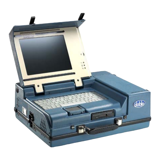
M4000 Insulation Analyzer
User Guide
Doble Engineering Company
85 Walnut Street
Watertown, Massachusetts 02472-4037
(USA)
PN 500-0110
72A-1230 Rev. F
Table of
Contents
Previous
Page
Next
Page
1
2
3
4
5
Advertisement
Table of Contents
Troubleshooting
M4100 Instrument Troubleshooting
91
Troubleshooting Resources
92
Detailed Troubleshooting Of The M4100 Instrument
95
Troubleshooting from Symptoms
102
Troubleshooting from Error Messages
106
Troubleshooting from Diagnostics
111
Need help?
Do you have a question about the M4000 series and is the answer not in the manual?
Ask a question
Questions and answers
Related Manuals for doble M4000 series
Measuring Instruments doble M4100 User Manual
Insulation analyzer (204 pages)
Measuring Instruments doble M4300 User Manual
Insulation analyzer (204 pages)
Measuring Instruments doble SFRA User Manual
Sweep frequency response analyzer (126 pages)
Measuring Instruments doble Vanguard Instruments WRM-10P S2 User Manual
Transformer winding resistance meter (77 pages)
Measuring Instruments doble TDR900 User
(78 pages)
Measuring Instruments doble Calisto H1 User Manual
(36 pages)
This manual is also suitable for:
M4200c
M4100
M4300
M4150
M4151
Table of Contents
Save PDF
Print
Rename the bookmark
Delete bookmark?
Delete from my manuals?
Login
Sign In
OR
Sign in with Facebook
Sign in with Google
Upload manual
Upload from disk
Upload from URL


Need help?
Do you have a question about the M4000 series and is the answer not in the manual?
Questions and answers