
Subscribe to Our Youtube Channel
Related Manuals for Brigade Backeye 360 HD


Summary of Contents for Brigade Backeye 360 HD
- Page 1 ® Backeye 360 HD BN360-300 Calibration, Installation & Operation Guide Please refer to https://brigade-electronics.com/ for most up-to-date data on all products Calibration, Installation & Operation Guide PN 5804A...
-
Page 3: Table Of Contents
3.1.3 Video input harness – BN360-VIN-01 ......8 Backeye 360 HD Configuration Tool ..26 3.1.4 Video output harness – BN360-VO-01 ......8 Using the Backeye 360 HD Configuration Tool ..26 3.1.5 Power harness - BN360-PWR-01 ........ 8 3.1.6 Interface harness – BN360-INT-01 ......8 3.1.7 Select Video Output Cable –... -
Page 4: Introduction To Backeye®360 Hd
Operators of the vehicle to which the Brigade Backeye®360 HD system is fitted must be made fully aware of how to interpret the images provided by the system so they will not be distracted by or rely completely on it. Distraction can cause accidents. -
Page 5: Display Configurations
360° surround view image above (for rear camera) or below (for front/side camera) the single camera views. The default view and triggered views can be assigned in the Backeye 360 HD Configuration Tool. View Configurations The system is capable of storing 10 different views per configuration (Landscape or Portrait):... -
Page 6: Views Modes
Views Modes The View Modes are the different views that the system can display in each Display Mode. Examples images of the view modes listed above are shown in the table below: View Description Example Image “Top” refers to the 360° birds-eye/surround Top + rear view Top + front view view image, the vehicle image is centered... -
Page 7: Crossing Traffic View
The extreme corners of the camera image can appear heavily distorted. Brigade recommends that this view is not used for manoeuvring the vehicle, this should only be used only to monitor the corner areas before switching to a normal view. -
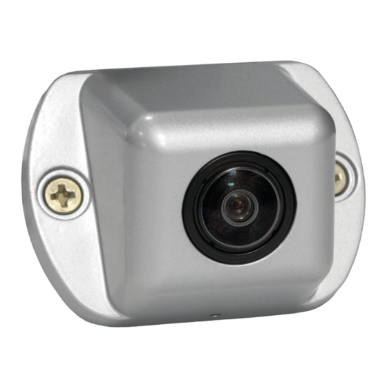
Page 8: System Components
Select Video Output Cable – BN360-VBV-L4015 3.1.7 The Video Output Cable provides the Main Interface Harness the ability to connect to Brigade VBV style monitors. Set-Up & View Select Button – BN360-CP-01 3.1.8 The Set-Up & View Select Button is used for calibration and changing the view. -
Page 9: Calibration Tools
The USB contains all documentation, software and support files required to install and calibrate the BN360-300 system, including the Brigade Backeye® 360° Calibration Software. For the latest USB contents please visit the Product Support Area on the Brigade Electronics website: https://brigade-electronics.com/product-support-area/. -
Page 10: Sd Card Data
SD Card Data SD Card Contents The SD Card contains all the necessary files to capture images from the cameras, perform camera position calibration and upload the calibration data. The SD Card Data can be found on the BN360-300-USB in the “3.0 SD Card Data” folder. -
Page 11: Hardware Installation
Hardware Installation Connection Diagram Please Note: Camera extension cables are not included in the kit and must be purchased seperately. Individual camera extension cable lengths should not exceed 25 meters. Item Part No. Qty. Model No. 5833 BN360-300-ECU 5807 BN360-300-ECU-FIX 4489 BN360-CP-01 4698... -
Page 12: Camera Installation
Camera position corrected with mounting bracket. It may be necessary to mount the cameras on a horizontal plane, such as under slung on the vehicle body. Brigade Electronics has a range of mounting brackets, e.g. BN360-100C-BKT01 which can be shaped to fit various installation... -
Page 13: Camera Mounting Height
5.2.2 Camera Mounting Height The mounting height of the camera is crucial to the quality of the 360° image. Typically, cameras mounted higher on a vehicle will produce a better 360° surround view image however the minimum mounting height will be dependent on a number of variables i.e. -
Page 14: Monitor
Monitor The monitor should be fixed in a suitable location for the operator and in line with any current legislation/regulations. The system can be installed in landscape or portrait view orientations therefore it may be necessary to rotate the monitor by 90°. Default System displayed on a monitor in Landscape Portrait configuration displayed on a monitor rotated position... -
Page 15: Vehicle Calibration
Step 4 > Calibrate camera positions using Backeye 360 HD Calibration Tool Step 5 > Configure view and trigger settings using Backeye 360 HD Configuration Tool (skip if not required) Step 6 > Upload calibration and configuration data (if required) to BN360-300 system Step 7 >... -
Page 16: Camera Image Collection
Camera Image Collection Before continuing it is recommended to always format the SD Card before calibration. With the vehicle ignition off, insert the Calibration Tool into the BN360- 300-ECU and turn the vehicle ignition ON. The following screen will be shown: Copy the “Backeye360HD”... -
Page 17: Installing The Backeye 360 Hd Calibration Software
® Installing the Backeye 360 HD Calibration Software Install the Calibration Software from the BN360-300-USB (2.0 Software folder) by double clicking the set-up file and following the instructions. Ensure the latest version of the software is used, visit Brigades website to download the current version. ®... -
Page 18: Loading The Config File
6.5.2 Loading the Config File Click the “Config Load” button and when the Config Load window opens, click the “o” icon to locate the Config file. Navigate to the configuration file location, this can be found in in the “Config” folder on the SD Card. The Config file name contains the configuration type and the revision number, e.g. -
Page 19: Calibration Control Points
6.5.4 Calibration Control Points The triangles in the calibration pattern are automatically detected and the Front & Rear Camera View control points are displayed. The software automatically detects the corners of the triangles and derives the coordinates of each image when loaded. The order of the control points starts from the triangle point closest to the vehicle and working clockwise to the other two points. -
Page 20: Surround View Preview
6.5.5 Surround View Preview Clicking the “Apply AVM” button will open the surround view “Preview” window. If there is anything wrong with the control points the “Calibration Error” prompt will be displayed with a hint describing which camera is incorrect. This is generally due to two errors: The control points are not correctly aligned. - Page 21 For standard Brigade Calibration Mats, the Length of Marker details do not need to be changed (the default value is 1500mm). For Calibration Mats that are not standard Brigade size, enter the width of the Calibration Triangle here. Set the Vehicle Dimensions to the dimensions of the vehicle used.
- Page 22 Horizontal and vertical adjustments can be made to remove any camera blind spots (shown in red) or any undesirable image distortion (see bottom left). Once the preferred mask position has been established, check to see that there is no excess vehicle body or camera blind areas (red area) shown.
-
Page 23: Parking Line Property
For the best results, Brigade recommends that the vehicle image is correctly scaled to fit the vehicle mask using the “Manual Fitting” option. -
Page 24: Guide Lines
Vehicle Dimensions • Tread – changes the width of the parking guides • Wheel base – the distance between the vehicle wheels, used in conjunction with the Steer Angle. Preview • World Coordinate – use the grid image to design the parking guides (as shown above) •... - Page 25 Select the save location for the calibration data when the following prompt is shown. Choose the SD Card (e.g. F:\Removable Disk). Select the check boxes for “Save control points” and “Save config” to save the calibration data in a new config file. This allows the user to reload the current or previous calibrations and make any changes if required without having to go through all the steps listed above again.
-
Page 26: Backeye 360 Hd Configuration Tool
To start, select a default configuration from the Tools > Set Default menu. The option chosen here should match the configuration used for the Backeye 360 HD Calibration Software, e.g. if it is a Landscape configuration, chose the Landscape option. - Page 27 By default the Parking Guide Line is set to “Trigger Only”. If a Parking Guide Line is configured in the calibration tool this will be displayed on the Backeye 360 HD system when the given trigger is active. By default the Speed Signal Trigger is set to off. Select the “On” option to enable this.
- Page 28 “Main View Mode” is the group of views that are displayed when the Set-Up & View Select Button is pressed. “Sub View Mode” is the second group of views that can be displayed by long pressing the Set-Up & View Select Button and pressing the button again to cycle through the views in this group.
- Page 29 When the TLV file is saved the tool bar will update with the TLV filename. Saved TLV files can be loaded into the Backeye 360 HD Calibration Tool by selecting the “Load TLV File” option in the “File” menu.
-
Page 30: Installing Calibration Data
Installing Calibration Data Once the calibration data has been saved to the SD Card as per section 6, insert the Calibration Tool into the BN360-300-ECU and apply power to the system. The “UPDATE SYSTEM” screen should be displayed prompting the user to insert an SD Card. Ensure the SD Card contents are correct and the “cmd”... -
Page 31: Checking System Functionality
Checking System Functionality It is important to check to see if the output is normal after the ECU resets. Ensure all blended areas are fully tested to make sure there are no blind spots around the vehicle. It is recommended to get an assistant to walk around the vehicle in the surround view to evaluate the calibration. -
Page 32: Appendix 1: Surround View Image Blends
Appendix 1: Surround View Image Blends The Backeye 360 HD Calibration Software allows for custom “blends” to create the most suitable 360° surround view image. During the calibration procedure, the “Mask Type” option gives the following options for blending the front, rear and side cameras: ▪... - Page 33 Front or Rear cameras e.g. to avoid front wing mirrors. For the area that the FOV does not need to be adjusted Brigade recommends setting the FOV for that camera to 140° and the Blend Width to 10°, these values may need to be adjusted depending on the calibration but typically give the closest match to the Blend Auto option.
- Page 34 When the “Front” or “Rear FOV” is set to 0° or 180° the When the “Front” or “Rear FOV” is set to any a value “Blending Width” option has no effect since there is no other than 0° or 180° the amount of overlap between overlapping areas, e.g.
-
Page 35: Appendix 2: Creating Custom Guide Lines
Create the guides as desired and fill the background, including the vehicle size rectangle in black (RGB 0,0,0). Any colour that is RGB 0,0,0 will be deleted by the Backeye 360 HD Calibration Tool. In this example, the Guide Lines have been drawn to the left and right side of the vehicle. - Page 36 In the Backeye 360 HD Calibration Tool, select the view that the Guide Line Overlay will be applied to. In this example the Guide Lines were drawn to the left and right side of the vehicle so the Left Full and Right Full single camera views are selected.
-
Page 37: Appendix 3: System Information Screen
The system information screen can be displayed any time the system is powered on by pressing and holding the “Power” button on the “Set Up and View Select Button”. Brigade recommends using this as the preferred method for checking the System Information because there is no need for any additional equipment, e.g. -
Page 38: Appendix 4: System Backup Function
OSD configuration across a fleet of vehicles. Please note: Brigade recommends saving the calibration data from the Calibration Tool, for more information see section 6.5.10. The System Backup function should only be used where the calibration data is not available and the data is planned to be restored to the same vehicle with the cameras installed in exactly the same location (e.g. - Page 40 Installation & Operation Guide PN 5804A...
Need help?
Do you have a question about the Backeye 360 HD and is the answer not in the manual?
Questions and answers