Table of Contents
Advertisement
Quick Links
Advertisement
Table of Contents

Related Manuals for BTEK HRB


Summary of Contents for BTEK HRB
- Page 1 Bench Scales Installation Instructions AWT35-100028 Issue AA...
- Page 2 Copyright © 2020 B-TEK. All rights reserved. HRB_base_i_en_100028.book...
-
Page 3: Table Of Contents
Removing the handles ....................... 9 Chapter 3 Connections ........................... 10 Base Communications setting ..................11 Base configuration ......................11 Chapter 4 Option installation ........................13 Draft shield option ......................13 Underhook option ......................16 Column option ........................18 HRB Bench Scale Installation Instructions... - Page 4 HRB Bench Scale Installation Instructions...
-
Page 5: Chapter 1 General Information And Warnings
IMPORTANT: This equipment must be routinely checked for proper operation and calibration. Application and usage will determine the frequency of calibration required for safe operation. Always disconnect the interface cable from the indicator before starting any routine maintenance to avoid the possibility of electric shock. HRB Service Manual... -
Page 6: Cleaning The Machine
Interference Regulations of the Canadian Department of Communications. Le présent appareil numérique n’émet pas de bruits radioélectriques dépassant les limites applicables aux appareils numériques de la Classe A prescrites dans le Règlement sur le brouillage radioélectrique edicté par le ministère des Communications du Canada. HRB Service Manual... - Page 7 2.1. Figure 2.1 HRB large and small capacity bench scale bases The HRB base uses a family of digital load cells. The bases are constructed of die cast aluminum, with stainless steel load-receiving platters. The 35kg and 80kg bases have a rectangular stainless steel platter of the same dimensions as the base.
-
Page 8: Unpacking And Installation
Unpack the scale and check for any damage. Report damage to the shipping company immediately. 2.1.1 Removing the shipping stops Four colored shipping stops are installed under the platter of the 35 and 80kg HRB scales at the factory. Before you begin weighing, be sure to remove these stops. Refer Figure 2.2. -
Page 9: Leveling The Scale
Figure 2.3 Leveling foot and bubble level 2.2 Removing the handles If the need to remove the handles on the HRB base arises, follow these steps. Press the left side of the handle towards the center... -
Page 10: Chapter 3 Connections
In the table below, connections to TB3 show use of the indicator Serial Port 1. If using Serial Port 2, then use pin 3 for RX_BASE and pin 5 for TX_BASE. Below is the wiring information for the HRB to indicators, (only applies to indicators that support multi-base input):... -
Page 11: Base Communications Setting
ORANGE WHITE/ORANGE The HRB base has to be linked to an approved high end indicator. It uses one of the dedicated RS232 channels to correctly communicate to the base. Use one of the dedicated RS232 base to indicator cables as listed below... -
Page 12: Chapter 4 Option Installation
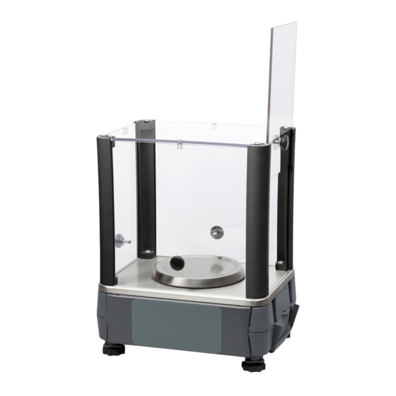
Draft shield option Option installation 4.1 Draft shield option These instructions cover the installation of the HRB draft shield kit, AWT05-508040. The kit consists of the parts shown below. A 5/32” hex wrench is also included. Hardware closeup Corner posts... - Page 13 Use a Phillips screwdriver and attach the top plate to the corner post using the four remaining screws. The draft shield is now complete. Each panel can slide up until the nylon spacer snaps into the small catch on the top plate. HRB Bench Scale Installation Instructions...
- Page 14 If static build- up occurs in the future, they can be sprayed with an anti-static spray or wiped down with a damp cloth. HRB Bench Scale Installation Instructions...
-
Page 15: Underhook Option
Option installation 4.2 Underhook option These instructions cover the installation of the HRB underhook kit, AWT05-507965. Assemble the parts to look like this final assembly. Tools needed: 1/4” open end wrench to tighten long standoffs Phillips screwdriver 11/32” nut driver small straight blade screwdriver(s) Note that there is a nut that is installed above the hook. - Page 16 Tighten both screws. These photos show the finished assembly, the left one with the base on its side and the other under the base as it will be used for weighing operations using the underhook. HRB Bench Scale Installation Instructions...
-
Page 17: Column Option
Parts in the kit include the column, three screws and two adjustable feet. To install the column, follow these steps: Lay the HRB and the column on their sides as shown in the photo below. Run the interface cable from the indicator through the hole in the base of the column and plug it into the proper scale connector. - Page 18 Set the scale on a flat surface and adjust the feet downward until they contact the table surface. Be sure they do not change the level of the scale. They should just support the column without lifting it. HRB Bench Scale Installation Instructions...
- Page 20 B-TEK Scales, LLC 1510 Metric Ave. SW Canton, OH 44706-3088...
Need help?
Do you have a question about the HRB and is the answer not in the manual?
Questions and answers