Ashcroft GC35 Quick Start Instructions
Heavy duty digital pressure sensor
Hide thumbs
Also See for GC35:
- Quick start instructions (4 pages) ,
- Installation and maintenance manual (20 pages)
Table of Contents
Advertisement
Quick Links
Quick Start Function Instructions for
GC35 Heavy Duty Digital Pressure Sensor
Version 1.0 6/06/09
(See Complete I&M Manual for Further Detail)
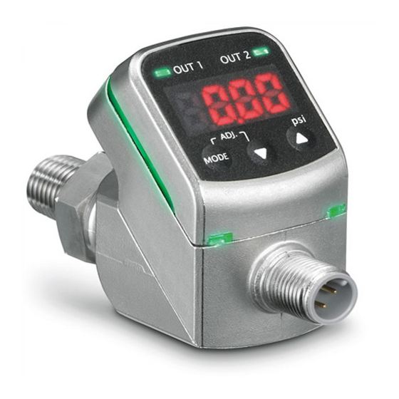
DISPLAY OVERVIEW
Collector/switch 1
LED operation indicator
(OUT 1)
4 Digit, 8mm
LED display
MODE key
DOWN key
Designation
Measurement Display
Mode Key
Down Key #
Up Key $
Collector / Switch LED
Operation Indicator
(OUT1)/(OUT2)
Switch Setting Mode LED
Operation Indicator (SET)
Note: Unit requires M12 mating connector p/n# 611C175-03
(standard 3 foot length) – see below.
2.00˝
© 2010 Ashcroft Inc., 250 East Main St., Stratford, CT 06614-5145, USA, Tel: 203-378-8281, Fax: 203-385-0499,
www.ashcroft.com All sales subject to standard terms and conditions of sale.
8/10 I&M011-10182-GC35 Ver. 6.03 Rev. B
All manuals and user guides at all-guides.com
Display of pressure, linear scaling
Change to/from switch setting modes and
MODE
product's settings
Change selections / decrease set values
Change selections / increase set values
Indicates switch state. LED indicator will be ON
when switch is activated
Identifies that the switch setting has been
performed
3´.00˝
Collector/switch 1
LED operation
indicator (OUT 2)
Setting mode
LED operation
indicator (SET)
UP key
Function
Advertisement
Table of Contents

Related Manuals for Ashcroft GC35


Summary of Contents for Ashcroft GC35
- Page 1 (standard 3 foot length) – see below. 2.00˝ 3´.00˝ © 2010 Ashcroft Inc., 250 East Main St., Stratford, CT 06614-5145, USA, Tel: 203-378-8281, Fax: 203-385-0499, www.ashcroft.com All sales subject to standard terms and conditions of sale. 8/10 I&M011-10182-GC35 Ver. 6.03 Rev. B...
- Page 2 All manuals and user guides at all-guides.com 1. Measurement Mode is entered when applying power to the unit – LED displays applied pressure. 2. Available “Measurement Mode” functions: Zero Adjustment: Press MODE / # keys together 3 seconds. This initiates automatic zero adjustment;...
- Page 3 All manuals and user guides at all-guides.com Function Setting Mode Menu Measurement Mode MODE MODE Press less than 3 sec. Press 3 sec. or longer Comparator Setting Mode Loop Check Mode Select with After 1 second keys Comparator 1 Use/No Use Message displayed Current setting In use...
- Page 4 All manuals and user guides at all-guides.com 4. Comparator-Switch / Loop Check Mode: Access by pressing MODE for less than 3 seconds. Comparator-Switch Setting: To activate / deactivate comparator-switch, scroll to US1 (4-20mA version only) or US2 and select USE / noU. Enter com- parator-switch set point by selecting A-1 or A-2 and use #/$ keys for pres- sure setting.
Need help?
Do you have a question about the GC35 and is the answer not in the manual?
Questions and answers