Advertisement
Product Information Page
PROGRAMMING THE GC30 DIFFERENTIAL PRESSURE TRANSMITTER TO
MONITOR THE CLOGGING OF HVAC FILTER
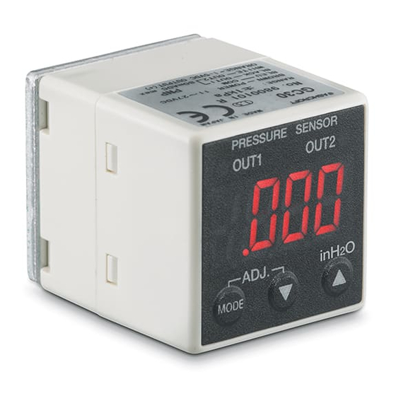
The GC30 differential pressure transmitter is compact and flexible instrument
that supports many applications and is often used to monitor the clogging of
filters. It can be easily programmed to measure the pressure in IWC to monitor
and control the clogging on an HVAC filter.
Monitoring and Controlling HVAC Filter:
This illustration demonstrates the use of GC30 differential pressure transmitter to monitor the clogging
of an air filter. Most industrial filters have a pressure drop of 0.170 IWC with industry common practice
to replace filters when the pressure drop reaches 0.500 IWC to prevent unnecessary maintenance while
protecting the system from failing due to blockage. See principles of operation diagram below for
reference.
All specifications are subject to change without notice.
All sales subject to standard terms and conditions.
© 2017 Ashcroft Inc.
Figure 1 - GC30 Differential Pressure Transmitter
Air Flow
Air Flow
Figure 1 - Filter Monitoring Diagram
ashcroft.com
info@ ashcroft.com
1.800.328.8258
PIP #: TR-PI-103
Applicable to:
GC30
Rev. A 02/17, Page 1 of 7
Advertisement
Table of Contents

Subscribe to Our Youtube Channel
Related Manuals for Ashcroft GC30


Summary of Contents for Ashcroft GC30
- Page 1 Figure 1 - GC30 Differential Pressure Transmitter Monitoring and Controlling HVAC Filter: This illustration demonstrates the use of GC30 differential pressure transmitter to monitor the clogging of an air filter. Most industrial filters have a pressure drop of 0.170 IWC with industry common practice to replace filters when the pressure drop reaches 0.500 IWC to prevent unnecessary maintenance while...
- Page 2 Product Information Page HVAC Filter Monitoring Application: This example uses a GC30 differential pressure transmitter with 0 to 1.00 IWC range with two NPN switches. The transmitter shall be programmed to activate the audible alarm when differential pressure reaches 0.500 IWC with output 1 switch and to shut down the system if differential pressure reaches 0.750 IWC with output 2 switch by using external relays with normally open contacts for the audible...
- Page 3 GC30 Transmitter Output Switches Configuration Method: Method to program GC30 transmitter set points. Output 1 shall be set at .500 IWC to activate the audible alarm, output 2 set at .750 IWC to shut down the heating/cooling system and both outputs shall reset at .200 IWC by setting the hysteresis of output 1 at .300 IWC and output 2 at .550 IWC.
- Page 4 100% FS (5 V at 1.00 IWC). Press and release MODE button to select and move to the next step. GC30 Transmitter Switch Set Point and Dead Band Set Up Method: Press and hold MODE button less than three seconds to get into program mode.
- Page 5 After verification press and hold MODE button for more than three seconds to return to measuring mode. All specifications are subject to change without notice. ashcroft.com Rev. A 02/17, Page 5 of 7 All sales subject to standard terms and conditions. info@ ashcroft.com © 2017 Ashcroft Inc. 1.800.328.8258...
- Page 6 Output 1 switch changes to normal state (OFF). Audible alarm turns OFF. All specifications are subject to change without notice. ashcroft.com Rev. A 02/17, Page 6 of 7 All sales subject to standard terms and conditions. info@ ashcroft.com © 2017 Ashcroft Inc. 1.800.328.8258...
- Page 7 Verify voltage reading (0 V dc). Switch changes to normal state (OFF). All specifications are subject to change without notice. ashcroft.com Rev. A 02/17, Page 7 of 7 All sales subject to standard terms and conditions. info@ ashcroft.com © 2017 Ashcroft Inc. 1.800.328.8258...
Need help?
Do you have a question about the GC30 and is the answer not in the manual?
Questions and answers