GE JB860 Quick Start Manual
Hide thumbs
Also See for JB860:
- Owner's manual (64 pages) ,
- Owner's manual (64 pages) ,
- Owner's manual (64 pages)
Advertisement
Quick Links
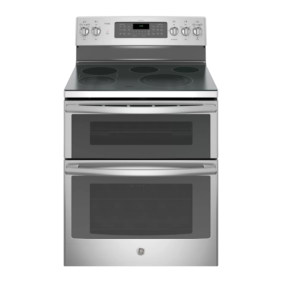
30" RADIANT FREE-STANDING RANGE
WARNING
Electrical Shock Hazard
Death or serious injury can result from failure to follow these
instructions.
• Service by a qualified service technician only.
• Disconnect power before servicing this product.
• Reconnect all grounding devices after service.
• Replace all parts and panels before operating.
NOTE: Installation
WARNING
information for reference
only. See Installation
Tip-Over Hazard
Instructions shipped with
A child or adult can tip the range and be killed.
product for complete
Verify the anti-tip bracket has been properly installed
and engaged.
details and before
Ensure the anti-tip bracket is re-engaged when the range
attempting to install.
is moved.
Anti-tip bracket must be
Do not operate the range without the anti-tip bracket in
place and engaged.
attached to the floor or
Failure to follow these instructions can result in death or
wall to hold either right or
serious burns to children or adults.
left rear leveling leg. Make
sure leveling leg re-engages the bracket when range is moved for any reason.
Adjacent Cabinet
Attachment to Wall
Bracket
Or Final Location
or Floor
Of Range Side Panel
Wall
Floor-Wood
Screw Must Enter
Wood or Metal
Bracket Side
Rear
Leveling Leg
Floor-Concrete
RADIANT HEATING ELEMENT SYSTEMS
The radiant heating element consists of a spiral-wound resistance wire attached
to microporous insulation with molded ceramic fiber walls in a corrosion-
protected metal tray.
The Heating Elements come in various sizes:
• 6" – 240 Volt, 1200 Watts
• 9"/6" – 240 Volt, 3100 Watts
• 12"/9" – 240 Volt, 3000 Watts
• Warmer – 240 Volt, 80 Watts
TEMPERATURE LIMIT/HOT LIGHT SWITCH
The Temperature Limit/Hot Light Switch performs two functions:
1. Turns on HOT LIGHT when the Surface Unit Switch is turned on. The hot light will
remain on until the glass surface above the heating unit has cooled below 150°F
(even after surface unit switch has been turned off).
2. Detects when glass temperature above a unit has exceeded its limit of approximately
1031°F and disconnects power to that unit. When glass temperature cools below
1031°F, the unit will turn back on. The temperature limit/hot light switch cannot be
calibrated.
SH. 1 of 4
31-17195-2
DUAL CIRCUIT CONTROL
This element has two cooking zones:
• To use the large cooking area, push to turn the control
knob clockwise to the desired setting.
• To use the small cooking area, push to turn the control
knob counterclockwise to the desired setting.
When a cooking zone is activated, coils beneath the zone
radiate heat through the glass cooktop to the utensil. The
red glow of the coils will be visible through the glass. It will
take the cooking zone on the glass surface a few moments
to heat up. The coil cycles on and off to maintain the
selected setting.
CONTROL PANEL ASSEMBLY REMOVAL
The control panel contains the control and infinite heat switches.
To Service:
1. Remove 2 screws (from bottom) securing control panel assembly
to the backguard endplates.
2. Remove 4 screws at the top, in the back of the range.
3. Pull bottom of panel out while lifting panel up.
4. Lay panel assembly on cooking surface.
CAUTION:
Place a protective covering (such as a towel) between
the control panel and the cooking surface to avoid damage to the control panel.
REMOVABLE OVEN DOORS
Wall Plate
Oven
To Remove the Upper Oven Door:
Frame
1. Fully open the door.
2. Lift up on the hinge locks toward the oven frame until
they stop.
3. Close the door to 45 degrees (you will feel the door
stop). The hinge lock will contact the oven frame.
4. On both sides of the door, press down on the release
buttons on each hinge.
5. Lift up the door until it is clear of the hinge.
6. Pull on the hinge arms lightly to relieve pressure
Door
Frame
on the locking tabs.
7. Push down the hinge locks onto the hinge.
8. Push in the hinges toward the unit so they are closed.
Release
To Replace the Upper Oven Door:
Buttons
1. Pull down the hinges away from the oven frame
to the fully open position.
2. Lift up on the hinge locks toward the oven frame until
Push In
they stop.
3. The hinges will release to the 45-degree position.
The hinge locks will contact the oven frame.
4. Slide the door back onto the hinges. Make sure
the buttons pop back out.
5. Fully open the door.
Pull Down
6. Push down the hinge locks onto the hinge.
7. Close the oven door.
To Remove the Lower Oven Door:
Hinge Lock
Slot
1. Fully open the door.
2. Push down the hinge locks
toward the door frame, to
the unlocked position. This
Hinge
may require a flat-blade
Arm
screwdriver.
3. Firmly grasp both sides of the door at the top.
4. Close the door to the door-removal position.
5. Lift up the door until the hinge arm is clear of the slot.
To Replace the Lower Oven Door:
Hinge
Arm
1. Firmly grasp both sides of the door at the top.
With the door at the same angle as the removal
Bottom
position, seat the indentation of the hinge arm into
Edge
the bottom edge of the hinge slot.
of Slot
2. Fully open the door.
3. Push up the hinge locks against the front frame
Indentation
of the oven cavity, to the locked position.
Hinge
4. Close the oven door.
Lock
Cooling Airflow:
Air enters the door assembly through large slots in the
bottom and flows upward between the inner and outer
assemblies, exhausting through slots in the top of the
door. DO NOT INSULATE THIS AIR CHANNEL.
To Service Upper and Lower Full-Glass Doors:
1. Complete door assembly:
• Remove the four screws from the bottom door frame.
• Remove the screws on each side of the door.
• The liner assembly and outer glass panel assembly can now be separated.
• Remove the four screws from the side posts at the bottom.
• Remove the four screws from the handle at the top of the handle bracket.
NOTE: On some doors, the bottom trim is sealed to the outer door glass
and cannot be separated.
2. Liner assembly:
• Remove the two screws on each side of the door liner to remove the door hinge
assembly.
• Remove the eight screws (6 for upper) from the insulation retainer.
• Remove the insulation retainer and then the insulation.
• The window pack is now accessible on units with a window door.
Door Gasket:
The door gasket is clipped into the liner of the door panel.
To Service Gasket
A gap must be left in the upper door gasket at bottom of door. The gap is required
to provide air flow in the oven for proper baking results.
Door panel
Gasket
Upper Gasket - Open
COOKTOP REMOVAL
650-02Q
To Remove:
1. Disconnect power.
2. Remove the 2 screws securing the front
of the cooktop to the chassis.
3. Prop up the cooktop, and unplug the
Hinge Pins
connectors at the back by squeezing the side
tabs. Remove the screw securing the ground
wire.
4. Lift up the back end of the cooktop about
Cooktop
2 inches to unhook the hinge pins from the
Mounting
brackets.
Screws
5. Reverse the process to reinstall.
Removal Position
cooktop too high can break the glass.
CAUTION:
voltage is connected to oven. The Electronic Oven Control system consists of the
control, daughter relay board, oven sensor, door and lock assembly.
NOTE: Temperature/Mode Selection necessary for operation of Relay contacts.
VOLTAGE MUST BE PRESENT ACROSS TERMINALS L1 TO N FOR CONTROL TO OPERATE.
Terminals
Broil COM (pin 1) to QTH NO (pin 2)
L1-1 to N
L1-2 to N
L2-1 to N
L2-2 to N
L1-1 to BAKE1
L1-1 to BROIL1
L1-2 to BAKE2
L1-2 to BROIL2
L1-2 to Conv2
J902-1 to N
*J903-1 to N (Lower Cavity)
*L1 to J6-3 Daughter Board
(Upper Cavity)
J903-2 to N (Lower Cavity)
J6-7 to N (Upper Cavity)
*Oven light not working. Make the following checks:
• Check oven light bulb.
Door panel
• Light is to come on when door is opened—check voltage across light socket.
Terminals should read 120VAC. If 0 volts, check jamb switch and wiring.
Gasket
• Light is to come on when control light pad is pressed. K906 or K1 daughter board
should click. Check voltage from L1 to J6-3 on daughter board (upper) or J903-1
to N (lower). Should read 120VAC. If 0 volts, replace the control.
Lower Gasket - Closed
OVEN SENSOR AND DOOR SWITCH OHMMETER TEST
(See "Motorized Door Lock Operation" for door switch function explanation.)
Remove power from oven. Make resistance meas ure ment from side of sensor and lock
switch connector with exposed terminals disconnected from control.
* If abnormal reading is
observed, wiggle leads
at connector at rear of
cavity between broil
element pins. If any
variation, replace sensor.
CAUTION:
Raising the
UPPER AND LOWER
OVEN SENSOR
AND LOCK SWITCH
CONNECTOR
ELECTRONIC OVEN CONTROL
Components are electrically HOT on control when
CONTROL VOLTAGE
Voltage
120 VAC all the time
240 VAC when cooking mode is active and
oven is not calling for heat
120VAC when Convection fan is turning CCW
120 VAC when light is on
120 VAC locking or unlocking
CIRCUIT
TERMINALS
OHMS
UPPER
LOWER
OVEN
OVEN
Oven Sensor
4 to 5
4 to 10
1100Ω @ Rm Temp.*
28000Ω @ CLEAN Temp.
Door Unlatched
1 to 2
1 to 8
Open
Door Latched
1 to 2
1 to 8
0Ω
Advertisement

Subscribe to Our Youtube Channel
Related Manuals for GE JB860


Summary of Contents for GE JB860
- Page 1 30” RADIANT FREE-STANDING RANGE DUAL CIRCUIT CONTROL To Replace the Lower Oven Door: ELECTRONIC OVEN CONTROL Hinge CAUTION: 1. Firmly grasp both sides of the door at the top. This element has two cooking zones: With the door at the same angle as the removal Components are electrically HOT on control when •...
- Page 2 KEY PANEL TEST MOTORIZED DOOR LOCK SPECIAL FUNCTIONS SERVICE MODE Power must be cycled within 2 hours before user can enter Service Mode. To enter 1. Touch each pad on the Key Panel. The motorized door lock assembly is located above the The control has a section that can be entered to change how the control will work.
- Page 3 SH. 3 of 4 31-17195-2...
- Page 4 SH. 4 of 4 31-17195-2...
Need help?
Do you have a question about the JB860 and is the answer not in the manual?
Questions and answers