
Related Manuals for General Pump SMH


Summary of Contents for General Pump SMH
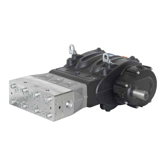
- Page 1 Repair Manual General Pump is a member of the Ref 300894 Rev. B Interpump Group 05-22...
-
Page 2: Table Of Contents
SMH SERIES GENERAL PUMP A member of the Interpump Group INDEX INTRODUCTION ..........Page 3 REPAIR INSTRUCTIONS . -
Page 3: Introduction
A member of the Interpump Group 1. INTRODUCTION This manual describes the instructions for Repairing SMH Series pumps, and must be carefully read and understood before performing any repair intervention on the pump. Proper pump operation and longevity depend on the correct use and maintenance. General Pump declines any responsibility for damage caused by the misuse or the non-observance of the instructions described in this manual. -
Page 4: Disassembly Of Mechanical Parts
SMH SERIES GENERAL PUMP A member of the Interpump Group 2.1.1 Disassembly of Mechanical Parts The correct sequence is the following: Completely empty the pump of oil, then disassemble the casing cover (and relative o-ring), unscrewing the (6) M10 screws (1, fig. 2). - Page 5 SMH SERIES GENERAL PUMP A member of the Interpump Group Position the 3 grub screws or M8 threaded screws (1, fig. 5) with the function of extractors in the holes and two sufficiently long M10 screws with the function of supporting the cover (2, fig. 5).
- Page 6 SMH SERIES GENERAL PUMP A member of the Interpump Group Separate the pinion from the cover, working with an extractor hammer on the pinion itself (1, fig. 8) Remove the Seeger ring Ø 55 (1, fig. 9) and the bearing support ring (1, fig. 10) from the pinion.
- Page 7 SMH SERIES GENERAL PUMP A member of the Interpump Group Unscrew the screws holding in the ring gear (1, fig. 12) and remove it (1, fig. 13). Remove the ring gear (1, fig. 14). Where necessary, it is possible to utilize an extractor hammer to be applied on the (2) M8 holes (2, fig.
- Page 8 SMH SERIES GENERAL PUMP A member of the Interpump Group Remove the ring gear support ring (1, fig. 16). Unscrew the connecting rod screws (1, fig. 17). Remove the connecting rod caps with the lower semi-bearings, taking special care of the disassembly sequence during disassembly.
- Page 9 SMH SERIES GENERAL PUMP A member of the Interpump Group Advance the half supports completely in the direction of the hydraulic part to allow the crankshaft to come out. To facilitate this operation, use special too part #F27566200 (1, fig. 19).
- Page 10 SMH SERIES GENERAL PUMP A member of the Interpump Group Position the 3 grub screws or M8 threaded screws (1, fig. 23) with the function of extractors in the holes and two sufficiently long M10 screws with the function of supporting the reduction gear box (2, fig. 23).
- Page 11 SMH SERIES GENERAL PUMP A member of the Interpump Group Position the 3 grub screws or M8 threaded screws (1, fig. 28) with the function of extractors in the holes. Slowly screw in the 3 M8 screws (1, fig. 29) to prevent the cover from tilting too far and getting locked in the housing.
- Page 12 SMH SERIES GENERAL PUMP A member of the Interpump Group In the event that it is necessary to replace one or more connecting rods or plunger guides, operate as follows: unscrew the screws with tool part #F27566200 to unlock the connecting rods (1, fig. 32) and then extract the connecting rod/plunger guide units from the back casing opening (1, fig.
- Page 13 SMH SERIES GENERAL PUMP A member of the Interpump Group Insert the pinion until the tool tooth enters completely into the oil seal (1, fig. 36). Continue rotating the pinion until the oil seal is completely removed (1, fig. 36a) fig.
- Page 14 SMH SERIES GENERAL PUMP A member of the Interpump Group Remove the spindle (1, fig. 38) and extract the connecting rod (1, fig. 39). Couple the half supports to the previously disassembled caps, referring to the numbering (1, fig. 40).
-
Page 15: Assembly Of Mechanical Parts
SMH SERIES GENERAL PUMP A member of the Interpump Group 2.1.2 Assembly of Mechanical Parts Proceed with assembly following the reverse order indicated in point 2.1.1. The proper sequence is as follows: Assemble the rod to the plunger guide. Insert the plunger guide rod into its seat on the plunger guide (1, fig. - Page 16 SMH SERIES GENERAL PUMP A member of the Interpump Group Block the three units with the use of special tool part #F27566200 (1, fig. 32) Pre-assemble the ring inside the crankshaft bearings (on both sides of the shaft down to the stroke) using special tool part #F27604700 (1, fig.
- Page 17 SMH SERIES GENERAL PUMP A member of the Interpump Group Fully insert the shaft in the casing (1, fig. 50 and fig. 51). Pre-assemble the outer ring of the pinion bearing on the reduction gear with the aid of special tool part #F27604900 (1, fig.
- Page 18 SMH SERIES GENERAL PUMP A member of the Interpump Group Repeat this operation on the bearing box, preassembling the external crankshaft bearing ring with the help of special tool part #F27605000 (1, fig. 56), inserting fully down to end stroke (1, fig. 57).
- Page 19 SMH SERIES GENERAL PUMP A member of the Interpump Group Tighten the (8) M10x30 screws (1, fig. 61). Calibrate the screws with a torque wrench as indicated in Section 3 “Screw Tightening Calibration”. From the opposite side, insert the side seal on the reduction gear box (1, fig. 62) and lift the crankshaft to favor cover insertion (1, fig.
- Page 20 SMH SERIES GENERAL PUMP A member of the Interpump Group Tighten the (8) M10x40 screws (1, fig. 65). Calibrate the screws with a torque wrench as indicated in Section 3, “Screw Tightening Calibration”. Remove the tool for blocking the connecting rods tool part #F27566200 (1, fig. 32) Insert the upper half-bearings between the connecting rods and the shaft (1, fig.
- Page 21 SMH SERIES GENERAL PUMP A member of the Interpump Group After finishing this operation, verify that the connecting rods have axial clearance in both direction. Insert the plunger guide seal rings in their casing by means of special tool part #F27605300. Position the component on the rod (1, fig.
- Page 22 SMH SERIES GENERAL PUMP A member of the Interpump Group Take care to fully and properly insert the o-ring in its housing on the cover to prevent them from being damaged during screw tightening. Calibrate the screws with a torque wrench as indicated in Section 3, “Screw Tightening Calibration”.
- Page 23 SMH SERIES GENERAL PUMP A member of the Interpump Group Fasten the ring gear stop (1, fig. 77) using (2) M10x25 screws. Calibrate the screws with a torque wrench as indicated in Section 3, “Screw Tightening Calibration” (1, fig 78).
- Page 24 SMH SERIES GENERAL PUMP A member of the Interpump Group From the other side of the pinion, pre-assemble the bearing 55x120x29 (1, fig. 82) positioning it to end stroke using tool #F27604800 (1, fig. 83). Insert the bearing support ring (1, fig. 84) and position the Seeger ring Ø 55 (1, fig. 85).
- Page 25 SMH SERIES GENERAL PUMP A member of the Interpump Group Insert the Seeger ring Ø 120 in the housing (1, fig. 87). Assemble the reduction gear cover with the aid of an extractor hammer (1, fig. 88) and fasten them with (7) M10x40 screws (1, fig.
- Page 26 SMH SERIES GENERAL PUMP A member of the Interpump Group To prevent damage to the seal ring, take special care when inserting the seal ring on the opinion. Apply o-rings on the inspection covers (1, fig. 92) and tighten with (2) M6x14 screws (1, fig. 93). Calibrate the screws with a torque wrench as indicated in Section 3 “Screw Tightening Calibration”.
-
Page 27: Increase And Reduction Classes
SMH SERIES GENERAL PUMP A member of the Interpump Group 2.1.3 Increase and Reduction Classes INCREASE TABLE FOR CRANKSHAFT AND CONNECTION ROD HALF-BEARINGS Correction on the shaft pin Recovery classes Half-bearing Half-bearing diameter (mm) Upper Lower (mm) 0.25 F90928100 F90928400 Ø79.75 0/0.02 Ra 0.4 Rt 3.5... - Page 28 SMH SERIES GENERAL PUMP A member of the Interpump Group Unscrew two diametrically-opposite M16 x 80 head fixing screws (1 and 2, fig. 96) and replace them with two service pin-screws (part #F27540200)(1, fig. 97), and then proceed to remove the remaining screws.
- Page 29 SMH SERIES GENERAL PUMP A member of the Interpump Group Remove the M10x140 head liner fixing screws (1, fig. 100) and remove the liner units (1, fig. 101). During assembly of the liners, take care not to disperse the valve springs and the flat valves (1 and 2, fig.
- Page 30 SMH SERIES GENERAL PUMP A member of the Interpump Group Extract the valve housings and check the conditions of the various components. If necessary, make any replacements (1, fig. 104). At every valve inspection, always replace all seal rings and relative o-rings between the liner and head, between the head and liner spacer in the recirculation inlet area.
-
Page 31: Assembling The Head-Liners-Valves
SMH SERIES GENERAL PUMP A member of the Interpump Group 2.2.2 Assembling the Head-Liners-Valves To reassemble the various components, reverse the operations listed previously, paying particular attention to the correct assembly of the spacer for liners: the hole Ø6 (seal cooling circuit) must correspond to the same hole for the head (with o-ring). - Page 32 SMH SERIES GENERAL PUMP A member of the Interpump Group Remove the M8x100 screws that fix the LP seals supports, HP seals support and liner as shown in fig. 111 , and proceed to the separation of all the components as indicated in fig. 112 and fig. 112a.
-
Page 33: Assembling The Plunger Unit-Supports-Seals
SMH SERIES GENERAL PUMP A member of the Interpump Group With separate HP seals support and a special pin (3, fig. 115), make the H.P. (high pressure) packing come out (4, fig. 116) finally extract the head ring (fig. 117). - Page 34 SMH SERIES GENERAL PUMP A member of the Interpump Group - Insert in the H.P. seals support, the head ring (1, fig. 119) and then the H.P. (high pressure) packing; con- sidering the slight interference between the seal and the H.P. seals support, to avoid damage we advise using a plastic pad (1, fig.
- Page 35 SMH SERIES GENERAL PUMP A member of the Interpump Group fig. 122 fig. 122a fig. 123 fig. 124 fig. 125 Insert the anti-extrusion ring (2, fig. 123) and the gasket bush (3, fig. 124) arranged as shown in fig. 125.
- Page 36 SMH SERIES GENERAL PUMP A member of the Interpump Group fig. 126 fig. 127 fig. 129 fig. 128 Reassemble the seals support unit as shown in Fig. 128 and 129 replacing components pos. 1, 2, 3. fig. 130 Assemble the L.P. and H.P. seals support units. – liner manually screwing the screws M8x100 as indicated in Fig.
-
Page 37: Screw Calibration
SMH SERIES GENERAL PUMP A member of the Interpump Group 3. SCREW CALIBRATION Screws are to be fastened exclusively using a torque wrench. Exploded View Position Fastening Fastening Description (From Owner’s Manual) Ft. Lbs. Casing cover M10x30 screw 33.2 G1/2x13 casing plug 29.5... - Page 38 SMH SERIES GENERAL PUMP A member of the Interpump Group Ref 300894 Rev. B 05-22 Page 38...
-
Page 39: Repair Tools
SMH SERIES GENERAL PUMP A member of the Interpump Group 4. REPAIR TOOLS Pump maintenance may be carried out using simple tools for assembling and disassembling components. The following tools are available: For Assembly: • Shaft (connecting rod interlocking)....... F27566200 •... -
Page 40: Maintenance Log
SMH SERIES GENERAL PUMP A member of the Interpump Group 5. MAINTENANCE LOG HOURS & DATE OIL CHANGE GREASE PACKING REPLACEMENT PLUNGER REPLACEMENT VALVE REPLACEMENT GP Companies, Inc. 1174 Northland Drive Mendota Heights, MN 55120 Phone:651.686.2199 Fax: 800.535.1745 Ref 300894 Rev. B www.generalpump.com email: sales@gpcompanies.com...
Need help?
Do you have a question about the SMH and is the answer not in the manual?
Questions and answers