
Related Manuals for SISTEMATICA Classic EASY


Summary of Contents for SISTEMATICA Classic EASY
- Page 1 C l a s s i c MANUALE D’USO • MANUEL DE L’UTILISATEUR • BENUTZERHANDBUCH • USER MANUAL...
-
Page 3: Table Of Contents
I prodotti descritti nel presente manuale sono conformi alla Direttiva 2014/53/EU ITALIANO La dichiarazione di conformità dei prodotti Sistematica S.r.l è disponibile all’indirizzo web www.sistematica.it/docs/DeclarationOfConformityClassic.pdf MANUALE D’USO AVVERTENZE RICEVITORI COPYRIGHT CARATTERISTICHE TECNICHE ......................................................... ABBREVIAZIONI E SIMBOLOGIA .......................... INSTALLAZIONE .............................. -
Page 4: Avvertenze
Al rilascio del tasto la/le uscite corrispondenti sul ricevitore rimangono attivate. Verranno disattivate alla successiva pressione del tasto. Sistematica S.r.l. si riserva il diritto di apportare, in qualsiasi momento e senza = NOTE, AVVERTENZE, SEGNALAZIONI preavviso, modifiche e miglioramenti ai prodotti per incrementare le qualità,... -
Page 5: Palmari
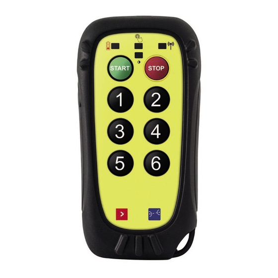
PALMARI CARATTERISTICHE TECNICHE Costruttore: Sistematica S.r.l. EASY (RESCUE - NEMO - NIMBLE - LIFT) Grado di protezione: IP67 Numero di tasti: fino a 6 (oltre a START & STOP) Temperatura di funzionamento: -20°C ÷ +55°C Dimensioni (mm): 109 x 56 x 30... -
Page 6: Batterie
BATTERIE Quando il LED rosso sul palmare si accende alla pressione di un tasto, si- gnifica che le batterie sono quasi scariche. Le prestazioni del sistema pos- sono risultare ridotte e bisogna procedere al più presto alla sostituzione. Per ragioni di sicurezza qualsiasi tasto premuto sarà interpretato come un comando di STOP. - Page 7 Dichiarazione per AEE Domestiche, contenenti Pile o Accumulatori ricaricabili e removibili, nei quali la batteria può essere facilmente rimossa dall’utilizzatore. INFORMAZIONE AGLI UTENTI DI APPARECCHIATURE DOMESTICHE Ai sensi dell’art. 26 del Decreto Legislativo 14 marzo 2014, n. 49 “Attuazione della Direttiva 2012/19/UE sui rifiuti di apparecchiature elettriche ed elettroniche (RAEE)”...
-
Page 8: Accensione Del Sistema
ACCENSIONE DEL SISTEMA CAMBIO PAGINA 1. Alimentare il CONTROLLER abbinato al palmare (vedere PAIRING p. 16 in Il sistema è composto da una trasmittente (palmare) e da una ricevente (Controller). A partire dallo START SISTEMA il controller esce dallo stato di caso di mancato abbinamento) e attendere qualche secondo. -
Page 9: Opzioni
OPZIONI TUTORIAL SAFETYPOINT SAFETYPOINT™ QRCode La tecnologia SafetyPoint™ rende sicuro l’azionamento dei palmari e riduce i rischi d’incidenti evitando di causare danni a persone o cose nei pressi delle parti in movimento, oltre che all’utilizzatore stesso. Il palmare dotato di SafetyPoint™ aziona i comandi programmati solo se si trova vicino ad una placchetta SafetyPoint™... -
Page 10: Pulsante Di Emergenza
PULSANTE DI EMERGENZA È un’opzione che aiuta a garantire il controllo completo delle operazioni Tra i vari avvisi, i LED sono quelli più visivi ed immediati per cui sono situati ogni volta che si renda necessario un arresto di emergenza dell’applica- in testa al palmare. - Page 11 LED SUL PALMARE Il palmare è dotato di 3 led utilizzati per indicare il funzionamento del sistema. Nella seguente tabella vengono descritti i vari significati. FUNZIONAMENTO SIGNIFICATO Lampeggia 1 volta Pressione di un tasto Lampeggia 6 volte Perdita link radio VERDE Lampeggia ogni 5 sec.
-
Page 12: Ricevitori
RICEVITORI CARATTERISTICHE TECNICHE Costruttore: Sistematica S.r.l. CNTR 4 (RADIOCAN - CNTRNIMBLE/PLUS) Grado di protezione: IP66 (CNTR4 = IP68) Numero di uscite: fino a 4 Temperatura di funzionamento: -20°C ÷ +55°C Numero di ingressi digitali: fino a 1 Tensione di alimentazione: 10/30V ±10%... -
Page 13: Installazione
CNTR 20 INSTALLAZIONE Dimensioni (mm): 133,2 x 154,2 x 44 Numero di uscite massime: fino a 20 di cui Al fine di garantire un corretto funzionamento, è necessario rispettare le - Numero di uscite proporzionali: 1 (ne perde 2) seguenti regole: - Numero di ingressi digitali: fino a 8 (perde uscite) ·... - Page 14 CNTR 8 CNTR 20 MONTAGGIO MONTAGGIO DIMA DI FORATURA DIMA DI FORATURA...
- Page 15 CNTR 32 RADIOCAN (protocollo J1939 o proprietario) MONTAGGIO 80 mm 68 mm PROFONDITÀ DIMA DI FORATURA 55 mm...
-
Page 16: Procedura Di Pairing
PROCEDURA DI PAIRING Per i sistemi non aggiornati all’ultima versione con la procedura del PAIRING MANUALE: 1. Togliere alimentazione al controller. Il PAIRING è un’operazione necessaria solo nel caso in cui si debba sostituire 2. Aprirlo svitando le due viti a fianco del connettore (CNTR8 e CNTR20) o le il ricevitore o si voglia utilizzare lo stesso con un palmare diverso da quello quattro viti sul fondo (CNTR32). -
Page 17: Opzioni
OPZIONI ANTENNA ESTERNA INSTALLAZIONE ANTENNA (CNTR32) L’antenna esterna ha la funzione di migliorare la capacità di ricezione del Il ricevitore CNTR32 viene fornito con antenna esterna (STUB) e relativa guarnizione. CONTROLLER nei casi in cui quest’ultimo debba essere montato in posizioni Essa deve essere montata sul connettore SMA sul retro del controller. -
Page 18: Tastiera D'emergenza
TASTIERA DI EMERGENZA PAIRING DEL SISTEMA CON TASTIERA DI EMERGENZA CNTR8 - CNTR20 Il controller dotato di tastiera di emergenza permette di effettuare il PAIRING La tastiera di emergenza permette l’utilizzo del sistema nel caso in cui le in modo semplice e pratico, senza dover aprire il controller: batterie del palmare si siano esaurite, nel caso in cui il palmare vada perso 1. -
Page 19: Tilting Hand (Uscita Proporzionale)
TARATURA DELLA VALVOLA PROPORZIONALE TILTING HAND La procedura di taratura permette di impostare la velocità minima e massima di movimentazione memorizzandoli nel CONTROLLER. I ricevitori CNTR20 e CNTR32 hanno la possibilità di comandare un’uscita in 1. Con il sistema acceso, premere contemporaneamente i tasti START e STOP modo proporzionale (accelerometro): sul palmare per almeno due secondi, fino a che il LED ROSSO sul palmare si alla pressione di un tasto e con il palmare in posizione di partenza orizzontale,... -
Page 20: Cablaggi
CABLAGGI Il cablaggio del CNTR4/CNTRNIMBLE/CNTRNIMLEPLUS è integrato al ricevitore con terminazione a fili liberi dall’altro capo. I CNTR 8 - CNTR 20 - CNTR 32 hanno un cablaggio standard da un metro con connettore SICMA FCI Header 24 poli femmina (CNTR8 e CNTR20) o dal connettore SICMA FCI Header 56 poli femmina (CNTR32), e con fili liberi sull’altro capo del cavo. -
Page 21: Individuazione E Risoluzione Dei Problemi
INDIVIDUAZIONE E RISOLUZIONE DEI PROBLEMI PROBLEMA POSSIBILI CAUSE SOLUZIONE • Verificare che il fungo di emergenza del palmare (se presente) sia in posizione di rilascio Mancanza di alimentazione del gruppo ricevente • Verificare che la fonte di alimentazione sia collegata in modo corretto al controller Collegamento errato del cablaggio Verificare il cablaggio verso le utenze (segnali, elettrovalvole etc.) verso le utenze... -
Page 22: Etichette
ETICHETTE PALMARI QR CODE Produttore (S/N - ART - SW) Modello Codice Direttiva RAEE Numero di serie Certificazione Europea Potenza Temperatura Protezione di esercizio internazionale Rif. ordine Certificazione USA... - Page 23 SCATOLA RICEVITORE Produttore Potenza Temperatura di esercizio Certificazione Automotive Direttiva RAEE Certificazione Europea Protezione internazionale...
- Page 24 FRONTALINO RICEVITORE QR CODE (S/N - ART - SW) Numero di serie Rif. ordine Modello Codice Certificazione USA...
- Page 26 Les produits décrits dans ce manuel sont conformes à la directive 2014/53/UE FRANÇAIS La déclaration de conformité des produits Sistematica S.r.l. est disponible à l’adresse Web www.sistematica.it/docs/DeclarationOfConformityClassic.pdf MANUEL DE L’UTILISATEUR AVERTISSEMENTS RÉCEPTEURS COPYRIGHT CARACTÉRISTIQUES TECHNIQUES ......................................................ABRÉVIATIONS ET SYMBOLES INSTALLATION ..........................
-
Page 27: Avertissements
à des tiers sous quelque des raisons de sécurité ainsi que pour une bonne conservation du produit. forme ou par quelque moyen que ce soit, sans que Sistematica S.r.l. ait Ils doivent être lus attentivement avant utilisation. Sistematica S.r.l. décline donné... -
Page 28: Palmaires
PALMAIRES CARACTÉRISTIQUES TECHNIQUES EASY (RESCUE - NEMO - NIMBLE - LIFT) Producteur: Sistematica S.r.l. Degré de protection: IP67 Nombre de touches: jusqu’à 6 (plus START & STOP) Température de fonctionnement: -20°C ÷ +55°C Dimensions (mm): 109 x 56 x 30... -
Page 29: Batteries
BATTERIES Quande la LED rouge de la télécommande s’allume lorsque vous appuyez sur un bouton, les piles sont presque vides. Les performances du système peuvent être dégradées et le remplacement doit être effectué dès que possible. Pour des raisons de sécurité, toute touche enfoncée sera interprétée comme une commande STOP. - Page 30 Déclaration pour les EEE domestiques, contenant des piles ou accumulateurs rechargeables et amovibles, dans lesquels la batterie peut être facilement retirée par l’utilisateur. INFORMATIONS AUX UTILISATEURS D’ÉQUIPEMENT DOMESTIQUE Conformément à l’art. 26 du décret législatif du 14 mars 2014, n. 49 «Mise en œuvre de la directive 2012/19/UE sur les déchets d’équipements électriques et électroniques (DEEE)»...
-
Page 31: Allumer Le Système
ALLUMER LE SYSTÈME CHANGEMENT DE PAGE 1. Mettre sous tension le CONTROLLER appairé à la télécommande (voir Le système se compose d’un émetteur (télécommande) et d’un récepteur (Controller). À partir du DÉMARRAGE DU SYSTÈME (START), le contrôleur sort PARING p. 39 en cas d’échec d’appairage) et attendre quelques secondes 2. -
Page 32: Options
OPTIONS TUTORIAL SAFETYPOINT SAFETYPOINT™ QRCode La technologie SafetyPoint™ rend les appareils portables sûrs et réduit le risque d’accidents en évitant de causer des dommages aux personnes ou aux choses à proximité des pièces mobiles, ainsi qu’à l’utilisateur lui-même. Le palmaire équipé de SafetyPoint™ exécute les commandes programmées uniquement s’il est situé... -
Page 33: Bouton D'urgence
BOUTON D’URGENCE LEDS Il s’agit d’une option qui permet d’assurer un contrôle complet des Parmi les différents avertissements, les voyants sont les plus visuels et les opérations chaque fois qu’un arrêt d’urgence de l’application est requis. plus immédiats, ils sont donc situés en haut de la télécommande. En appuyant sur le bouton, le CONTROLLER s’éteint et met à... - Page 34 LED SUR LE PALMAIRE Le Palmaire est équipé de 3 LEDs utilisées pour indiquer le fonctionnement du système. Les différentes significations sont décrites dans le tableau suivant. LEDS FONCTIONNEMENT SIGNIFICATION Clignote 1 fois Appuyant sur un bouton Clignote 6 fois Lien radio perdu VERTE Clignote toutes les 5 secondes...
-
Page 35: Récepteurs
RÉCEPTEURS CARACTÉRISTIQUES TECHNIQUES CNTR 4 (RADIOCAN - CNTRNIMBLE/PLUS) Producteur: Sistematica S.r.l. Degré de protection: IP66 (CNTR4 = IP68) Nombre de sorties: jusqu’à 4 Nombre d’entrées numériques: jusqu’à 1 Température de fonctionnement: -20°C ÷ +55°C Courant maximum disponible pour chaque canal: 5A Tension d’alimentation: 10/30V ±10%... -
Page 36: Installation
CNTR 20 INSTALLATION Dimensions (mm): 133,2 x 154,2 x 44 Nombre maximum de sorties: jusqu’à 20 Afin d’assurer un bon fonctionnement, les règles suivantes doivent être - Nombre de sorties proportionnelles: 1 (perd 2) respectées: - Nombre d’entrées numériques: jusqu’à 8 (en perdant des sorties) ·... - Page 37 CNTR 8 CNTR 20 INSTALLATION INSTALLATION GABARIT DE FORAGE GABARIT DE FORAGE...
- Page 38 CNTR 32 RADIOCAN (J1939 ou protocole propriétaire) INSTALLATION 80 mm 68 mm PROFONDEUR GABARIT DE FORAGE 55 mm...
-
Page 39: Procédure D'appariement (Pairing)
PROCÉDURE D’APPARIEMENT (PAIRING) Pour les systèmes qui ne sont pas mis à jour avec la dernière version, voici ci-dessous la procédure d’APPARIEMENT MANUEL: 1. Coupez l’alimentation du CONTROLLER. Le PAIRING est une opération nécessaire uniquement si vous devez remplacer 2. Ouvrez-le en dévissant les deux vis à côté du connecteur (CNTR8 et le récepteur ou si vous souhaitez l’utiliser avec un appareil portable autre que CNTR20) ou les quatre vis en bas (CNTR32). -
Page 40: Options
OPTIONS ANTENNE EXTERNE INSTALLATION D’ANTENNE (CNTR32) L’antenne externe a pour fonction d’améliorer la capacité de réception du Le récepteur CNTR32 est fourni avec une antenne externe (STUB) et un joint relatif. Il doit être monté sur le connecteur SMA à l’arrière du contrôleur. CONTROLLER dans les cas où... -
Page 41: Clavier D'urgence
CLAVIER D’URGENCE PAIRING DU SYSTÈME AVEC LE CLAVIER D’URGENCE CNTR8 - CNTR20 Le clavier d’urgence permet l’utilisation du système en cas d’épuisement Le controller équipé d’un clavier de secours permet d’effectuer le PAIRING de des piles de la télécommande, en cas de perte de la télécommande ou dans manière simple et pratique, sans avoir à... -
Page 42: Tilting Hand (Sortie Proportionnelle)
CALIBRAGE DE LA VANNE PROPORTIONNELLE TILTING HAND La procédure de calibrage vous permet de définir les vitesses de déplacem- ent minimales et maximales en les mémorisant dans le CONTROLLER. Les récepteurs CNTR20 et CNTR32 ont la capacité de contrôler une sortie 1. -
Page 43: Câblages
CÂBLAGE Le câblage du CNTR4/CNTRNIMBLE/CNTRNIMLEPLUS est intégré dans le récepteur avec une terminaison de fil libre à l’autre extrémité. Les CNTR 8 - CNTR 20 - CNTR 32 disposent d’un câblage standard d’un mètre avec embase femelle SICMA FCI 24 pôles (CNTR8 et CNTR20) ou avec embase femelle SICMA FCI 56 pôles (CNTR32), et avec fils libres sur l’autre extrémité... -
Page 44: Identification Et Dépannage
IDENTIFICATION ET DÉPANNAGE PROBLÈME CAUSES POSSIBLES SOLUTION • Vérifiez que le champignon d’urgence du palmaire est en position de déverrouillage Panne de courant du groupe récepteur • Vérifiez que la source d’alimentation est correctement connectée au contrôleur Connexion incorrecte du câblage Vérifiez le câblage aux services (signaux, électrovannes, etc.) aux services Le système ne... -
Page 45: Étiquettes
ÉTIQUETTES TÉLÉCOMMANDES QR CODE (S/N - ART - SW) Producteur Modèle Code Directive DEEE Numéro de série Certification Européenne Puissance Température de Protection fonctionnement internationale Référence Certification États-Unis de l’ordre... - Page 46 BOÎTE DE RECEPTION Producteur Puissance Température de fonctionnement Certification Automotive Directive DEEE Certification européenne Protection internationale...
- Page 47 FAÇADE DU RÉCEPTEUR QR CODE (S/N - ART - SW) Numéro de série Référence de l’ordre Modèle Code Certificazione USA...
- Page 49 Die in diesem Handbuch beschriebenen Produkte entsprechen der Richtlinie 2014/53/EU DEUTSCHE Die Konformitätserklärung der Produkte von Sistematica S.r.l finden Sie unter der Webadresse www.sistematica.it/docs/DeclarationOfConformityClassic.pdf BENUTZERHANDBUCH WARNHINWEISE EMPFÄNGER URHEBERRECHTE TECHNISCHE EIGENSCHAFTEN ....................................................... ABKÜRZUNGEN & SYMBOLE ..........................INSTALLATION ............................... HANDHELD KOPPLUNGSVERFAHREN (PAIRING) ....................
-
Page 50: Urheberrechte
Form oder in irgendeiner Weise an Dritte übertragen. Produktkonservierung bereitgestellt. Sie müssen vor Gebrauch sorgfältig gelesen werden. Sistematica S.r.l. lehnt jede Verantwortung ab, die sich aus ABKÜRZUNGEN & SYMBOLE der Nichtbeachtung der in diesem Handbuch angegebenen Warnungen ergibt. -
Page 51: Technische Eigenschaften
HANDHELDS TECHNISCHE EIGENSCHAFTEN Hersteller: Sistematica S.r.l. EASY (RESCUE - NEMO - NIMBLE - LIFT) Schutzart: IP67 Anzahl der Tasten: bis zu 6 (plus START & STOP) Betriebstemperatur: -20°C ÷ +55°C Abmessungen (mm): 109 x 56 x 30 Übertragungsentfernung: 150m im Freien und ohne Störung Stromversorgung: 2 AAA Alkaline 1,5V Batterien Typische Absorption in Ruhe: 5 ΜA... -
Page 52: Batterie
BATTERIEN Wenn die rote LED am Handheld beim Drücken einer Taste aufleuchtet, sind die Batterien fast leer. Die Systemleistung kann beeinträchtigt sein und ein Austausch sollte so bald wie möglich erfolgen. Aus Sicherheitsgründen wird jeder Tastendruck als STOP-Befehl interpretiert. Gehen Sie für einen korrekten Batteriewechsel wie folgt vor: 1. - Page 53 Erklärung für Haushalts-Elektro- und Elektronikgeräte mit wiederaufladbaren und austauschbaren Batterien oder Akkus, in denen die Batterie vom Benutzer leicht entfernt werden kann. INFORMATIONEN FÜR BENUTZER VON HAUSHALTSGERÄTEN Gemäß der Kunst. 26 des Gesetzesdekrets 14. März 2014, n. 49 “Umsetzung der Richtlinie 2012/19/EU über Elektro-und Elektronikaltgeräte (WEEE)” und des Gesetzesdekrets 188 vom 20.
-
Page 54: Einschalten Des Systems
SCHALTEN DES SYSTEMS PAGE CHANGE (SEITENWECHSEL) 1. Schalten Sie den mit dem Handheld gekoppelten CONTROLLER ein (siehe Das System besteht aus einem Sender (Handheld) und einem Empfänger (Controller). Mit dem START verlässt der Controller den Stand-by-Zustand KOPPELN S. 62, falls die Kopplung fehlschlägt) und warten Sie einige und baut die Funkverbindung zum Handheld auf (CloseLink). -
Page 55: Optionen
OPTIONEN TUTORIAL SAFETYPOINT SAFETYPOINT™ QRCode Die SafetyPoint™ -Technologie macht Handheld-Geräte sicher und verringert das Unfallrisiko, indem Schäden an Personen oder Gegenständen in der Nähe der beweglichen Teile sowie am Bediener vermieden werden. Der mit SafetyPoint™ ausgestattete Handheld führt die programmierten Befehle nur aus, wenn er sich in der Nähe einer SafetyPoint-Platte befindet. -
Page 56: Notfall Knopf
NOTFALL KNOPF LEDS Dies ist eine Option auf Handhelds, die dabei hilft, die vollständige Kontrol- Unter den verschiedenen Warnungen sind die LEDs am sichtbarsten und le über den Betrieb zu gewährleisten, wenn ein Notstopp der Anwendung unmittelbarsten, daher befinden sie sich oben auf dem Handheld. erforderlich ist. - Page 57 LEDS AN HANDHELD Der Handheld ist mit 3 LEDs ausgestattet, die die Funktionsweise des Systems anzeigen. Die verschiedenen Bedeutungen sind in der folgenden Tabelle beschrieben. OPERATION BEDEUTUNG Blinkt 1 Mal Ein Knopf wird gedrückt Blinkt 6 mal Funkverbindung verloren GRÜN Blinkt alle 5 Sek.
-
Page 58: Empfänger
EMPFÄNGER TECHNISCHE EIGENSCHAFTEN CNTR 4 (RADIOCAN - CNTRNIMBLE/PLUS) Hersteller: Sistematica S.r.l. Schutzart: IP66 (CNTR4 = IP68) Anzahl der Ausgänge: bis zu 4 Betriebstemperatur: -20°C ÷ +55°C Anzahl der digitalen Eingänge: bis zu1 Versorgungsspannung: 10/30V ±10% Maximal verfügbarer Strom für jeden Kanal: 5A... -
Page 59: Installation
CNTR 20 INSTALLATION Abmessungen (mm): 133,2 x 154,2 x 44 Maximale Anzahl von Ausgängen: bis zu 20 davon Um einen ordnungsgemäßen Betrieb zu gewährleisten, müssen die folgenden - Anzahl der proportionalen Ausgänge: 1 (durch Verlust von 2) Regeln beachtet werden: - Anzahl der digitalen Eingänge: bis zu 8 (Verlust der Ausgänge) ·... - Page 60 CNTR 8 CNTR 20 INSTALLATION INSTALLATION BOHRVORLAGE BOHRVORLAGE...
- Page 61 CNTR 32 RADIOCAN: (J1939 oder proprietäres Protokoll) INSTALLATION 80 mm 68 mm WEITE BOHRVORLAGE 55 mm...
-
Page 62: Kopplungsverfahren (Pairing)
KOPPLUNGSVERFAHREN (PAIRING) Für Systeme, die nicht auf die neueste Version aktualisiert wurden, hier unten das MANUELLE PAIRING-Verfahren: 1. Trennen Sie die Stromversorgung von der Steuerung. PAIRING ist nur dann ein notwendiger Vorgang, wenn Sie den Empfänger 2. Öffnen Sie es, indem Sie die beiden Schrauben neben dem Anschluss (CNTR8 ersetzen müssen oder ihn mit einem anderen Handheld-Gerät als dem und CNTR20) oder die vier Schrauben an der Unterseite (CNTR32) lösen. -
Page 63: Optionen
OPTIONEN CNTR32 ANTENNENINSTALLATION EXTERNE ANTENNE Der CNTR32-Empfänger wird mit einer externen Antenne (STUB) und einer Die externe Antenne wird verwendet, um die Empfangskapazität des entsprechenden Dichtung geliefert. Es muss am SMA-Anschluss auf der Rückseite CONTROLLERS in Fällen zu verbessern, in denen dieser an Positionen montiert des Controllers montiert werden. -
Page 64: Emergency Keyboard (Notfalltastatur)
EMERGENCY KEYBOARD SYSTEMKOPPELN MIT NOTFALLTASTATUR CNTR8 - CNTR20 Der mit einer Nottastatur ausgestattete Controller ermöglicht ein einfaches Die Notfalltastatur ermöglicht die Verwendung des Systems, falls die und praktisches PAIRING, ohne den Controller öffnen zu müssen: Batterien des Handhelds erschöpft sind, falls das Handheld verloren geht 1. -
Page 65: Tilting Hand (Proportional Ausgang)
KALIBRIERUNG DES PROPORTIONALVENTILS TILTING HAND Das Kalibrierverfahren ermöglicht es Ihnen, die minimale und maximale Bewegungsgeschwindigkeit einzustellen, indem Sie sie im CONTROLLER speichern. Die Empfänger CNTR20 und CNTR32 haben die Fähigkeit, einen Ausgang 1. Drücken Sie bei eingeschaltetem System die START- und die STOP-Taste am proportional zu steuern (Beschleunigungsmesser): Handheld gleichzeitig für mindestens zwei Sekunden, bis die ROTE LED am Auf Knopfdruck und bei horizontaler Ausgangslage des Handhelds wird... -
Page 66: Kabel
KABEL Das CNTR4/CNTRNIMBLE/CNTRNIMLEPLUS-Kabel ist im Empfänger integriert und hat am anderen Ende einen freien Drahtabschluss. Die CNTR 8 - CNTR 20 - CNTR 32 haben ein ein Meter langes Standardkabel mit SICMA FCI 24-poliger Buchsenleiste (CNTR8 und CNTR20) oder mit der SICMA FCI 56-poligen Buchsenleiste (CNTR32) und mit freien Drähten das andere Ende des Kabels. -
Page 67: Identifizierung Und Lösung Von Problemen
IDENTIFIZIERUNG UND LÖSUNG VON PROBLEMEN PROBLEM MÖGLICHE URSACHEN LÖSUNG • Überprüfen Sie, ob sich der Notfallpilz auf dem Handheld (falls vorhanden) in der Freigabeposition befindet Stromausfall der empfangenden Gruppe • Stellen Sie sicher, dass die Stromquelle ordnungsgemäß an die Steuerung angeschlossen ist Schlechte Kabelverbindung Sie die Verkabelung zu den Versorgungsunternehmen (Signale, Magnetventile usw.) Überprüfen... -
Page 68: Etiketten
ETIKETTEN HANDHELDS QR-CODE Produzent (S/N - ART - SW) Modell Code WEEE- Richtlinie Seriennummer Europäische Zertifizierung Leistung Betriebstemperatur Internationaler Schutz Bestellnummer USA-Zertifizierung... - Page 69 EMPFÄNGERBOX Produzent Leistung Betriebstemperatur Automotive- Zertifizierung WEEE- Richtlinie Europäische Zertifizierung Internationaler Schutz...
- Page 70 FRONTPLATTE DES EMPFÄNGERS QR CODE (S/N - ART - SW) Seriennummer Bestellnummer Modell Code Certificazione USA...
- Page 72 The products described in this manual comply with Directive 2014/53/EU ENGLISH The declaration of conformity of Sistematica S.r.l products is available at the web address www.sistematica.it/docs/DeclarationOfConformityClassic.pdf USER MANUAL WARNINGS RECEIVERS COPYRIGHT TECHNICAL FEATURES ..............................................................ABBREVIATIONS & SYMBOLS ........................... INSTALLATION ..............................
-
Page 73: Warnings
Sistematica S.r.l. reserves the right to make, at any time and without notice, = NOTES, WARNINGS, SIGNS modifications and improvements to the products to increase the quality, and... -
Page 74: Handhelds
HANDHELDS TECHNICAL FEATURES EASY (RESCUE - NEMO - NIMBLE - LIFT) Manufacturer: Sistematica S.r.l. Protection degree: IP67 Number of keys: up to 6 (plus START & STOP) Operating temperature: -20°C ÷ +55°C Dimensions (mm): 109 x 56 x 30 Transmission distance: 150m in open air and without interference Power supply: 2 AAA AlKaline 1,5V batteries Typical absorption at rest: 5 ΜA... -
Page 75: Batteries
BATTERIES When the red LED on the handheld turns on while pressing a button, the batteries are almost empty. System performance may be degraded and re- placement should be done as soon as possible. For safety reasons, any key pressed will be interpreted as a STOP command. For a correct battery replacement procedure, proceed as follows: 1. - Page 76 Statement for Domestic EEE, containing rechargeable and removable Batteries or Accumulators, in which the battery can be easily removed by the user. INFORMATION TO USERS OF DOMESTIC EQUIPMENT Pursuant to art. 26 of Legislative Decree 14 March 2014, n. 49 “Implementation of Directive 2012/19/EU on electrical and electronic equipment waste (WEEE)” and of Legislative Decree 188 of 20 November 2008.
-
Page 77: Switching On The System
SWITCHING ON THE SYSTEM PAGE CHANGE 1. Power up the CONTROLLER paired with the handheld (see PAIRING p. 85 in The system consists of a transmitter (handheld) and a receiver (Controller). Pressing START the controller exits the stand-by state and establishes radio case of failure to pair) and wait a few seconds. -
Page 78: Options
OPTIONS TUTORIAL SAFETYPOINT SAFETYPOINT™ QRCode SafetyPoint™ technology makes handheld devices safe and reduces the risk of accidents by avoiding causing damage to people or things near the moving parts, as well as to the operator. The handheld equipped with SafetyPoint™ operates the programmed commands only if located near a SafetyPoint Plate. -
Page 79: Emergency Button
EMERGENCY BUTTON LEDS This is an option on handhelds that helps ensure complete control of Among the various warnings, the LEDs are the most visual and immediate operations whenever an emergency stop of the application is required. so they are located at the top of the handheld. By pressing the button, the CONTROLLER switches off and all outputs are reset. - Page 80 LEDS ON HANDHELD The handheld is equipped with 3 LEDs used to indicate the functioning of the system. The various meanings are described in the following table. OPERATION MEANING Blinks 1 time A button is pressed Blinks 6 times Lost radio link GREEN Flashes every 5 sec.
-
Page 81: Receivers
RECEIVERS TECHNICAL FEATURES CNTR 4 (RADIOCAN - CNTRNIMBLE/PLUS) Manufacturer: Sistematica S.r.l. Protection degree: IP66 (CNTR4 = IP68) Number of outputs: up to 4 Operating temperature: -20°C ÷ +55°C Number of digital inputs: up to 1 Supply voltage: 10/30V ±10% Maximum current available for each channel: 5A... -
Page 82: Installation
CNTR 20 INSTALLATION Dimensions (mm): 133,2 x 154,2 x 44 Maximum number of outputs: up to 20 of which In order to ensure correct operation, the following rules must be respected: - Number of proportional outputs: 1 (by losing 2) ·... - Page 83 CNTR 8 CNTR 20 INSTALLATION INSTALLATION DRILLING TEMPLATE DRILLING TEMPLATE...
- Page 84 CNTR 32 RADIOCAN: (J1939 or proprietary protocol) INSTALLATION 80 mm 68 mm WIDTH DRILLING TEMPLATE 55 mm...
-
Page 85: Pairing Procedure
PAIRING PROCEDURE For systems that are not updated to the latest version, here below the MANUAL PAIRING procedure: 1. Remove power from the controller. PAIRING is a necessary operation only if you need to replace the receiver 2. Open it by unscrewing the two screws next to the connector (CNTR8 and or want to use it with a handheld device other than the one it was paired CNTR20) or the four screws on the bottom (CNTR32). -
Page 86: Options
OPTIONS EXTERNAL ANTENNA INSTALLAZIONE ANTENNA (CNTR32) CNTR32 ANTENNA INSTALLATION The External Antenna is used to improve reception capacity of the The CNTR32 receiver is supplied with an external antenna (STUB) and relative CONTROLLER in cases where the latter must be mounted in positions not gasket. -
Page 87: Emergency Keyboard
EMERGENCY KEYBOARD SYSTEM PAIRING WITH EMERGENCY KEYBOARD CNTR8 - CNTR20 The controller equipped with an emergency keyboard allows PAIRING to The emergency keyboard allows the use of the system in the event that the be carried out in a simple and practical way, without having to open the batteries of the handheld are exhausted, in the event that the handheld controller: is lost or in the event that, for any reason, it is not possible to control the... -
Page 88: Tilting Hand (Proportional Output)
CALIBRATION OF THE PROPORTIONAL VALVE TILTING HAND The calibration procedure allows you to set the minimum and maximum movement speeds by storing them in the CONTROLLER. The CNTR20 and CNTR32 receivers have the ability to control an output 1. With the system switched on, press the START and STOP buttons on the proportionally (accelerometer): handheld simultaneously for at least two seconds until the RED LED on the upon pressing a button and with the handheld in the horizontal starting... -
Page 89: Cables
CABLES The CNTR4/CNTRNIMBLE/CNTRNIMLEPLUS cable is integrated in the receiver with free wire termination on the other end. The CNTR 8 - CNTR 20 - CNTR 32 have a standard one-meter cable with SICMA FCI 24-pole female header connector (CNTR8 and CNTR20) or with the SICMA FCI 56-pole female header connector (CNTR32), and with free wires on the other end of the cable. -
Page 90: Problem Identification And Solutions
PROBLEM IDENTIFICATION AND SOLUTION PROBLEM POSSIBLE CAUSES SOLUTION • Check that the Emergency Mushroom on the handheld (if present) is in the release position Power failure of the receiving group • Verify that the power source is properly connected to the controller Bad wiring connection Check the wiring to the utilities (signals, solenoid valves etc.) The system does... -
Page 91: Labels
LABELS HANDHELDS QR CODE Producer (S/N - ART - SW) Model Code WEEE directive Serial number European certification Power Operating International temperature protection Order reference USA certification... - Page 92 RECEIVER BOX Producer Power Operating temperature Automotive certification WEEE directive European certification International protection...
- Page 93 RECEIVER FACEPLATE QR CODE (S/N - ART - SW) Serial number Order reference Model Code USA certification...
- Page 96 This product may be subject to restrictions in its use. More information can be requested by writing to info@sistematica.it s i s t e m a t i c a . i t Sistematica S.r.l. - Via Andrea Sansovino 217 - 10151 - Torino - Italia...
Need help?
Do you have a question about the Classic EASY and is the answer not in the manual?
Questions and answers