
Related Manuals for Albalá Ingenieros DAT3000C01


Summary of Contents for Albalá Ingenieros DAT3000C01
- Page 1 DAT3000C01 DUAL AES/EBU DIGITAL AUDIO SAMPLING RATE CONVERTER/DELAY LINE Version 1.0 Albalá Ingenieros, S.A. 21 December 2016 - © Albalá Ingenieros S.A. - All rights reserved Medea, 4 - 28037 Madrid - Spain...
- Page 2 DAT3000C01...
-
Page 3: Table Of Contents
DAT3000C01 DUAL AES/EBU DIGITAL AUDIO SAMPLING RATE CONVERTER/DELAY LINE Version 1.0 1. DESCRIPTION ........................5 1.1. The DAT3000C01 ..........................5 1.2. Features ............................. 6 1.3. Block diagram ..........................7 2. SPECIFICATIONS ......................... 9 3. INSTALLATION ........................11 3.1. Initial inspection .......................... 11 3.2. - Page 4 4.2.8.2. Operation in Automatic Mode ................27 4.2.8.3. Operation in Manual Mode ..................28 4.3. Module remote control and supervision ................29 4.3.1. Details of the DAT3000C01 registers ................30 5. GLOSSARY ........................33 6. REGULATIONS ........................35 7. VERSIONS ......................... 37...
-
Page 5: Description
32, 44.1, 48, 64, 88.2 or 96 kHz. If a frequency other than those listed is required, the DAT3000C01 can be operated in varispeed mode. A quartz crystal oscillator together with a digital direct synthesis circuit (DDS) is used to generate the master clock for the standard sampling frequencies, guaranteeing low jitter operation. -
Page 6: Features
• Module control and supervision can be done remotely when the mounting frame is equipped with a communications controller module. • One UR3000 mounting frame can house up to 12 DAT3000C01 modules. If power supply redundancy is required and FA3000 or FA3001 modules are used then only 10 modules can be housed in the mounting frame. -
Page 7: Block Diagram
Albalá Ingenieros | Manual DAT3000C01 1.3. Block diagram... - Page 8 Albalá Ingenieros | Manual DAT3000C01 DAT3000C01...
-
Page 9: Specifications
Albalá Ingenieros | Manual DAT3000C01 2. SPECIFICATIONS AES/EBU digital audio signal input Connector Plug-in terminal, 3.81 mm pitch Impedance 110 Ω ± 20 % Type Transformer balanced Encoding and electrical characteristics According to EBU Tech. 3250-E/AES3 standard Sampling rate 30 to 100 kHz... - Page 10 Albalá Ingenieros | Manual DAT3000C01 Type Passive Loop-Through or 75 Ω loaded Threshold levels: min. 2.0 V max. 0.8 V Black-burst reference signal input Connector Return loss >30 dB up to 5 MHz Type Passive Loop-Through or 75 Ω loaded Signal format According to ITU-R BT.470-6 standard...
-
Page 11: Installation
ELECTROSTATIC DISCHARGE. Always use antistatic bags clearly identified with a high degree of shielding for storage and transportation. The DAT3000C01 module is composed of two parts: one DAT3000P01 main board and one DAT3000P02 rear board. Both parts must be installed in a UR3000 or UR3100 mounting frame following the instructions in the corresponding section of this chapter. -
Page 12: Environmental Considerations
3.4. Power considerations The UR3000 and UR3100 mounting frames can house as many DAT3000C01 modules as will fit in them. 3.5. Module configuration The DAT3000C01 provides multiple program jumpers for configuration. -
Page 13: Selection Of 20 Or 24 Bits At The Input
3.5.1. Selection of 20 or 24 bits at the input The DAT3000C01 module can operate with the full 24 bits of the sampled audio received or keep only the 20 most significant bits. This selection is made via switch 1... -
Page 14: Termination Of The Delay Input
110. 3.5.6. Selection of automatic mode or manual mode for the reference input The DAT3000C01 module has two operating modes for selection of the reference input and the sampling frequency: automatic or manual. In automatic mode, the reference input and the sampling frequency are adjusted automatically based upon a prioritized set of criteria. -
Page 15: Selection Of The Sampling Frequency
- The coaxial reference set for black burst signal. 3.6. Installing the module in the mounting frame The steps needed to install the DAT3000C01 module with the rear board in the mounting frame are: 1 - Disconnect all power cords from the power supplies of the mounting frame. - Page 16 INSTALLATION section of this manual. 6 - Insert the DAT3000P01 board (main board of the DAT3000C01 module) into the front of the mounting frame. The edges of the card slide into two plastic guides inside the mounting frame.
-
Page 17: Interconnection
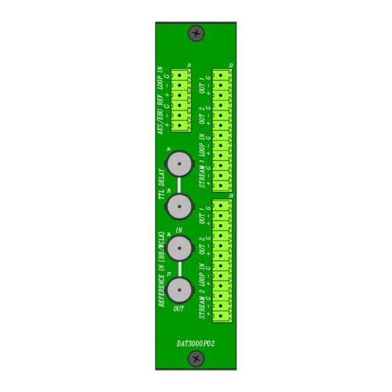
The following figure shows the DAT3000C01 module rear board connector layout. Rear view of the DAT3000C01 The DAT3000C01 module provides two loop-through inputs (STREAM 1 LOOP IN and STREAM 2 LOOP IN) and two outputs (OUT1 and OUT2) for each digital audio section. It also provides two loop-through inputs (AES/EBU REF. -
Page 18: Connections For Analog Video, Word-Clock And The Delay Signal
Keep in mind that this loop introduces a 0.4 dB attenuation, equivalent to a loss of 5% of the signal amplitude. Therefore, it is not recommended to have more than five DAT3000C01 units connected using loop-through. If more than five units will be used, the system engineer should perform the necessary calculations based upon the length of the cabling and the signal amplitude in order to guarantee that the signal level at the last module in the loop is always greater than 300 mVpp. -
Page 19: Operation
Albalá Ingenieros | Manual DAT3000C01 4. OPERATION This section describes the significance of the front panel indicators of the DAT3000C01 module and their remote control and monitoring ability. 4.1. Front panel description The appearance of the front panel and the elements it contains are shown in the following illustration. - Page 20 W.CLOCK: Blue. These are the reference input indicator LEDs. Each one corresponds to one of the three possible sync source inputs of the DAT3000C01, and they have two brightness levels. They light up at low brightness to indicate that a signal is present and then light up with full brightness to indicate that the corresponding input has been selected.
-
Page 21: Functional Description
Pushbuttons. These buttons are for adjustment of the desired delay. 4.2. Functional description This section describes the operation of the DAT3000C01. Given its complexity and the variety of sampling frequencies it can convert, it will be helpful to keep the following figure that shows the signal flow within the DAT3000C01 handy. -
Page 22: Description Of The Delay Line
If higher sampling frequencies are required at the output (64 to 192 kHz) then double frequency mode must be used. When the DAT3000C01 is used purely as a line delayer the frequency conversion can be disabled, providing the complete signal quality from the input to the output. This disabling can be done using the control software via a communications controller installed in the same mounting frame as the DAT3000C01. -
Page 23: Processing Of The Channel Status Bits
184 previous bits. The field corresponding to the source alphanumeric code (Block 2) is labeled DAT1'' in the first section of the DAT3000C01 and DAT2'' in the field corresponding to the second section. -
Page 24: Description Of The Processing Unit
23 bytes previous to the status channel. The content of bytes 14, 15, 16 and 17 are always zero coming from the DAT3000C01. The DAT3000C01 comes from the factory set to replacement mode, meaning that it substitutes the contents in Block 1, 2, 3 and 4 with the values stored in the module's memory. -
Page 25: And U Bits
The validity bit, V, is always set to 0. This indicates that the output streams of the DAT3000C01 contain audio in pulse code modification (PCM) format. Given its function, the DAT3000C01 does not process the user bits, which are always set to 0. -
Page 26: Operation In 20 Or 24 Bit Mode
DAT3000C01 4.2.6. Operation in 20 or 24 bit mode The DAT3000C01 can process audio streams of 20 or 24 bits, and this selection can be set for both the audio inputs and the outputs. 4.2.7. Operation in doubled sampling frequency mode The DAT3000C01 can function with AES/EBU signals that carry a monophonic signal at twice the sampling frequency. -
Page 27: Description Of The Synchronization
DAT3000C01 4.2.8. Description of the synchronization The DAT3000C01 includes a bank of switches for selection of the three synchronization modes. The first is Automatic Mode, where the modules selects the sampling frequency and the reference input automatically. The second is Manual Mode, where the user sets the reference input and the sampling frequency. -
Page 28: Operation In Manual Mode
The word-clock input admits a pulse train signal with TTL levels at a frequencies that should correspond to one of the standard values. If the frequency of the TTL signal is not a standard value then the DAT3000C01's oscillator will not be able to sync. -
Page 29: Module Remote Control And Supervision
Albalá Ingenieros | Manual DAT3000C01 4.3. Module remote control and supervision The DAT3000C01 can optionally be remotely controlled/supervised. In order to perform remote configuration and supervision of the module an optional TL3000 family remote communications controller must be installed in the mounting frame. -
Page 30: Details Of The Dat3000C01 Registers
- Supervision of the levels of the digital audio signals. 4.3.1. Details of the DAT3000C01 registers The DAT3000C01 module provides control and status registers that can be read and written by means of specific commands described in the communication control module user manuals. - Page 31 Albalá Ingenieros | Manual DAT3000C01 OUT_192K 0x01 0x80 Allows selecting 192kHz output 0=No, 1=Yes FIX_DELAY_1 0x02 0xFFFF Allows setting a fixed delay for AES1 = x samples FIX_DELAY_2 0x04 0xFFFF Allows setting a fixed delay for AES2 = x samples...
- Page 32 Albalá Ingenieros | Manual DAT3000C01 DAT3000C01...
-
Page 33: Glossary
Albalá Ingenieros | Manual DAT3000C01 5. GLOSSARY AES/EBU This acronym covers the combined AES and EBU standard for transmission of digital audio. The standard defines a serial interface known as AES3 as per AES, EBU 3250-E as per EBU or ITU-R BS.647-2 as per ITU. The interface originally transmitted two channels (one pair) with PCM coding with a bit depth of 20 or 24 bit and a sampling frequency between 32 kHz and 192 kHz. - Page 34 Albalá Ingenieros | Manual DAT3000C01 DAT3000C01...
-
Page 35: Regulations
Albalá Ingenieros | Manual DAT3000C01 6. REGULATIONS AES11 (2009) AES recommended practice for digital audio engineering - Synchronization of digital audio equipment in studio operations. AES3 (2003) AES Recommended practice for digital audio engineering - Serial transmission format for two-channel linearly represented digital audio data. - Page 36 Albalá Ingenieros | Manual DAT3000C01 DAT3000C01...
-
Page 37: Versions
Albalá Ingenieros | Manual DAT3000C01 7. VERSIONS Ver. Date Description 13-06-2013 Preliminary Version 21-12-2016 First version... - Page 38 Albalá Ingenieros, S.A. Medea, 4 - 28037 Madrid Spain +34 913274453 www.albalaing.com info@albalaing.com...
Need help?
Do you have a question about the DAT3000C01 and is the answer not in the manual?
Questions and answers