Table of Contents
Advertisement
Quick Links
Advertisement
Table of Contents

Subscribe to Our Youtube Channel
Summary of Contents for Willy WS-8450
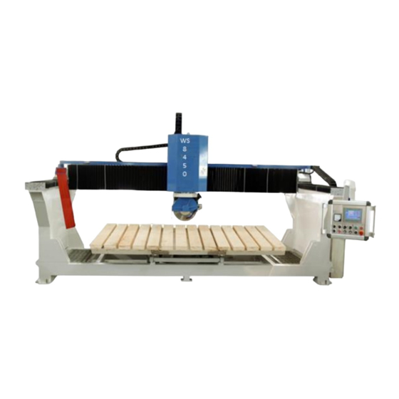
- Page 1 WS-8450 Bridge-Saw Operation Manual...
-
Page 2: Table Of Contents
Contents 1. Safety and Health Precautions ....................1 1.1 CAUTION .......................... 1 1.2 Graphic Symbols ......................2 1.3 Technical Data ......................... 3 2. Installation ..........................4 2.1 Lifting and Moving Machine .................... 4 2.2 Machine Leveling ......................4 2.3 Bridge Installation ......................6 2.4 Lubrification ............... -
Page 3: Safety And Health Precautions
Keep this manual in a safe place. Willy Industries reserves the right to make variations to the production and the manual. Failure to comply with the safety prescriptions or the improper use of the machine may cause damage to those articles in the operating area. -
Page 4: Graphic Symbols
1.2 Graphic Symbols WARNING SIGN SAFETY INSTRUCTIONS Operate by authorized people only. Risk of crushing one’s hands if this operation is not performed in compliance with safety regulations. Risk of electric shock if operation is not performed in compliance with safety regulation. -
Page 5: Technical Data
1.3 Technical Data Willy WS-8450 Max. work piece length 3300 Max. work piece width 2000 Max. work piece height Blade diameter 400--450 Max. spindle speed 2900 Blade rotate angle degree 0、90 Blade tilt angle 0-90 degree Table tilt angle 0-85... -
Page 6: Installation
2.Installation 2.1 Lifting and Moving the Machine Check that the equipment and accessories used to lift the machine (belts, cables, hooks) are capable of supporting the weight of the machine as indicated on the identification plate. Bring the machine down onto the floor with the greatest care avoiding sudden drops and hazardous jerks. -
Page 8: Bridge Installation
2.3 Bridge installation We remove some parts from both sides of bridge when shipping. The instructions bellow will inform how to install these loose parts: Shoulder extended part (1). Protection cover connection part (2). Metal sheet (3)(4). ... - Page 9 2.3.2 Other parts. We removed the following parts when shipping. You have to install them before using machine. Encoder (1). Pipeline (2). Hydraulic (3). Manual Grease (4). Cable trough (5).
- Page 10 2.4 Lubrication Both sides of bridge (1) and Beam (2) will need be lubricated in the oil bath. Oil level must be higher than linear guide and rack. Usually it uses engine oil or rail oil. After machine has been installed, please take dust cover off, then pour oil inside to lubricate the gear and guide of the X axis and Z axis.
-
Page 11: Operation
3.Operation 3.1 Axis reference 3.2 Turn on the machine Turn on main power. Turn on the emergency switch. Press the ‘Start’ switch. -
Page 12: Panel
3.3 Panel Number Picture Name Function Touch screen Ammeter Current of the spindle motor. Voltmeter Voltage of main power Left: Turn up table. Table flip switch Right: Turn down table... - Page 13 Left: rotate table anticlockwise. Table rotate switch Right: rotate table clockwise. X+, X-: Move X axis. Joystick axis motion XZ Z+,Z-: Move Z axis. Joystick axis Move Y axis. motion Y Spindle start Start spindle. Spindle stop Stop spindle. Laser Turn laser on/off.
-
Page 14: Hmi
Emergency stop Turn off the power of PLC. 3.4 HMI 3.4.1 Settings X axis cut Acc and Dec distance: Accelerate and decelerate distance at length direction when “cut of X axis”. I is used when blade start to cut into stone. Y axis cut Acc and Dec distance: Accelerate and decelerate distance at length direction when “cut of Y axis”. - Page 15 Lubricate machine manually. 3.4.2 Auto Cut of X axis: Blade cut along X axis when head at 0 degree. Cut of Y axis: Blade cut along Y axis when head at 90 degrees. Width: The distance between two adjacent cutting. Pieces: Specify number of pieces to be cut and width.
- Page 16 speed reaches a normal value. Auto mode can’t be triggered until this lamp turns to green. Machine will back to zero (initial) position when this command is triggered. 3.4.3 Manual Function of manual mode is to cut single line. Press X+(X-), machine executes X direction single cut when head at 0 degree. Press Y+(Y-), machine executes Y direction single cut when head at 90 degree.
- Page 17 : Rotate head to 90 degrees.
- Page 18 3.4.4 Profiling Profiling function is use to process all kinds of line or abnormal stone. Please make the profiling model before processing. Blade cuts along the model when blade is at 90 degrees. Parameters: Profiling Length(Y): Specify the profiling length at Y axis; Profile total length(X2): Specify profiling width at X axis.
- Page 19 3.4.5 Table Clear “Table current position” to 0 when table at 0 position. Start to rotate the table to direction which “Table rotation (deg)” specified. This function is enable in JOG Rotate mode. Specify table rotate mode, JOG or Auto. Jog mode: Table would rotate to the specify direction.
- Page 20 3.4.6 Joystick Joystick axis motion XZ. Joystick axis motion Y. We design special function of joystick axis motion when automatic cycle is running. System finish current cutting when you press Z+ direction, then machine moves to next step to continue auto cycle. This is useful if you set cutting length larger than product size.
-
Page 21: Example
3.5 Example 3.5.1 Cut of X axis Material size: 2000*1600 Product size: 2000*400, 2000*300 (2pieces), 2000*500. Parameter setting: Set the size (“width” and “pieces”) (1) of product. 400mm-1psc, 300mm-2psc, 500mm-1psc. As the diameter of blade is 470mm. Set “X axis cutting length” (2) 250-400mm larger than length of product. - Page 22 This parameter is saved on the system, please set it when you use the machine first time. Rotate head to 0 degree . Move blade to left corner of material (A). Start position is default “origin of X0”. Warning: Origin of blade must higher than top of stone. Otherwise blade will feed under stone at width direction, the blade maybe damaged.
- Page 23 3.5.2 Cut of Y axis Material size: 2000*1600 Product size: 500*1600(2pieces), 300*1600(2pieces). Parameter setting: Set the size (“width” and “pieces”) (1) of product. 500mm-2pcs, 300mm-2pcs. As the diameter of blade is 470mm. Set “Y axis cutting length” (2) 250-400mm larger than length of product.
- Page 24 Rotate head to 90 degrees . Move blade to left corner of material (B). Start position is default “origin of Y0”. Warning: Origin of blade must higher than top of stone. Otherwise blade will feed under stone at width direction, the blade maybe damaged. Press command to start Spindle on the operation panel, spindle indicate lamb turns to green...
- Page 25 3.5.3 Auto rotate Material size: 2000*1600 Product size: 1000*800(4 pieces). Parameter setting: Set the size (“width” and “pieces”) (1) of product. “Cut of X axis” 800mm-2pcs. “Cut of Y axis” 1000mm-2pcs. As the diameter of blade is 470mm. Set “X axis cutting length” and “Y axis cutting length” (2) 250-400mm larger than length of product.
- Page 26 Press (3) to rotate head to 90 degrees. Move blade to left corner of material (C). Press (4) to set the “origin of Y0”. Background of command changes to green Press (3) to rotate head to 0 degree. Move blade to left corner of material (D). Press (4) to set the “origin of X0”.
- Page 27 3.5.4 Manual cut Warming: Please remember to start spindle when execute manual cutting. 1200mm Cutting process: cut one single line along X axis 1200mm Rotate blade to 0 degree, move it to position A; Set cutting “Distance” 1200 Start spindle Press Machine start, Z axis feeds to top of table, then cuts along X axis.
- Page 28 executing Z feed. Press Y+ or Y- when head at 0 degree, machine feed along Y axis directly without executing Z feed.
- Page 29 3.5.5 Profiling Install the profiling mode (2) on the rack(1). Rotate blade to 90 degrees. Activate profiling mode: Click command on profiling screen, It changes to Choose profiling type: Roughing or finishing Set the value of ‘Z- limit’: This process should protect the cover of blade when profiling process outside the range of profiling model.
- Page 30 Turn on ‘Auto switch’ to start automatic cutting on the operation panel. Warming: 2 cutting modes are changed when profiling, please adjust before Auto cutting: Setting screen: Double direction mode would be active. Auto screen: “Multi Feed Cut” would active. Suspend profiling process: Turn ‘Auto switch’...
- Page 31 3.5.6 Table rotation Make sure Z axis is at up limit (Z+ limit) before rotate table. We can rotate table in two types. Jog mode: Table would rotate to the specify direction. Auto mode: Table would stop each 45 degree. Jog rotate.(2 types) Choose mode at HMI.
-
Page 32: Adjusts And Maintenance
4.Adjust and Maintenance 4.1 Hydraulic Adjust. 4.1.1 Table Rotating speed. (Table rotating speed has been setting normally before deliver.) Adjust speed of table when table is rotating. Manual rotate table use handle in table rotate mode. Press C+ to rotate table clockwise, press C- to rotate table anticlockwise. Table rotation speed adjust:... -
Page 33: Maintenance
4.2 Maintenance Before starting any maintenance operations disconnect the electrical power supply by setting the main switch to position OFF. Never use petrol, solvents or other inflammable liquids to clean the machine. EVERY DAY Clean away dust from the machine, particularly in the areas: floor around machine, worktable, mobile carriage. -
Page 34: Attachment
5. Attachment 5.1 Parameter Y axis positioning accuracy: Maximum permissible error of Y axis. X axis positioning accuracy: Maximum permissible error of X axis Z axis positioning accuracy: Maximum permissible error of Z axis Y axis decelerate distance: Decelerating distance at width direction when “cut of X axis”. X axis decelerate distance: Decelerating distance at width direction when “cut of Y axis”. -
Page 35: Input/Output
5.2 Input/Output A phase of Y axis I0.0 Q0.0 Forward encoder B phase of Y axis I0.1 Q0.1 Backward encoder Invert #1 fast speed(Y I0.2 #1 inverter alarm Q0.2 axis) A phase of X axis I0.3 Q0.3 Invert #1 low speed(Y axis) encoder B phase of X axis Invert #2 clockwise(XZ... - Page 36 I2.7 Hydraulic overload Q2.7 Table disc brake off I3.0 Table clockwise Q3.0 Head clockwise I3.1 Table anticlockwise Q3.1 Head anticlockwise I3.2 Table up Q3.2 Head cylinder brake off I3.3 Table down Q3.3 Head cylinder brake on I3.4 stop Q3.4 Table rotate low speed I3.5 Table at zero position Q3.5...
-
Page 37: Server Parameter
5.3 Servo parameter value Function 1-00 Maximum Output Frequency 1-04 Mid-Point Voltage 1-06 Minimum Output Voltage 1-08 Minimum Output Frequency 1-09 Accelerate Time 1-10 Decelerate Time 2-00 Source of Frequency 2-03 Source of Operation Command 5-00 60.00 1st Step Speed Frequency 5-01 2.500 2nd Step Speed Frequency... -
Page 38: Hydraulic System
5.4 Hydraulic system...
Need help?
Do you have a question about the WS-8450 and is the answer not in the manual?
Questions and answers