Table of Contents
Advertisement
Quick Links
Advertisement
Table of Contents

Related Manuals for Cloudray 3DM580S


Summary of Contents for Cloudray 3DM580S
- Page 1 3DM580S USER MANUAL 3DM580S USER MANUAL...
-
Page 2: Table Of Contents
3DM580S USER MANUAL Contents 1. Product Overview............................1 2.Application Environment and Installation....................... 1 2.1Environmental requirement........................1 2.2Drive installation dimensions........................2 3.Drive Port and Connection..........................3 3.1Port function description........................... 3 3.2 Power supply input..........................3 Motor connection..........................4 3.4 Control signal connection ........................4 3.4.1 IN Port: connection for pulse command...................4... -
Page 3: Product Overview
3DM580S type switch stepper drive is provided with the pulse train with S-shape acceleration/deceleration, and triggers the motor start-stop only by normal switching value.. -
Page 4: Drive Installation Dimensions
3DM580S USER MANUAL Vibration 0.5G(4.9m/s ) Max Operating temperature/humidity 0℃ ~ 45℃ / 90% RH or less (no condensation) Storage and transportation temperature: -10℃ ~ 70℃ Cooling Natural cooling / away from the heat source Waterproof grade IP54 2.2 Drive installation dimensions 22.5... -
Page 5: Drive Port And Connection
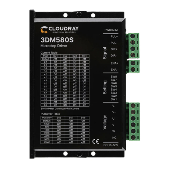
3DM580S USER MANUAL 3. Drive Port and Connection 3.1 Port function description Function Grade Definition Remarks Input V+ power supply AC 20~80V Power supply input port DC 24~100V Input V- power supply Motor connection port Motor UVW interface ENA+ Enable connection... -
Page 6: Motor Connection
When the drive is powered off, similarly, the drive LED indicator will be on if the load is increased to allow the motor to move 3.3 Motor connection The matching motor of the 3DM580S-IO drive is the low resistance and low inductance hybrid stepper motor. The common 3-phase stepper motor’s lead number are 3 and 6. 3.4 Control signal connection 3.4.1... -
Page 7: Ena Port: Enable/Disable
3DM580S USER MANUAL Dual Pulse (CW +CCW) Orthogonal Pulse(A/B) 3. 4.2 ENA port: enable/disable When the default optocoupler is off, the drive outputs the current to the motor. When the internal optocoupler is on, the drive will cut off the current of each phase of the motor so that the motor is in a free state, and the stepper pulse can not be responded. -
Page 8: The Setting Of Dip Switches And Operating Parameters
3DM580S USER MANUAL Difference 4. The setting of DIP switches and operating parameters The setting of current Semi / Full current option The setting of pulse per revolution www.cloudraymotor.com... -
Page 9: The Setting Of Current
3DM580S USER MANUAL 4.1 The setting of current Peak Current 备注 Default Other Current can be custom-made DIP SW1, SW2, SW3, SW4 are used to set current which is output from drive to motor. Generally, the current setting is the motor rated current. If your system has high request to the heating, please decrease the current properly to lower the motor’s heating, but at the same time, the output torque will be... -
Page 10: Pulse Filtering Function Selection
3DM580S USER MANUAL ※ The initial pulse is the testing pulse used when developing the drive software; Please refer to the actual running direction of the motor. 4.3 Pulse filtering function selection DIP SW6 is used to set the pulse filtering function of drive. -
Page 11: Common Faults And Troubleshooting
3DM580S USER MANUAL Green indicator is on for long time Drive not enabled Green indicator is flickering Drive working normally One green indicator and one red indicator Drive overcurrent One green indicator and two red indicators Drive input power overvoltage... -
Page 12: Appendix A. Guarantee Clause
3DM580S USER MANUAL The signal is disturbed Eliminate interference for reliable grounding Check the upper computer instructions to The command input is incorrect ensure the output is correct The position or speed The setting of Pulse per revolution is Check the DIP switch status and correctly... - Page 13 3DM580S USER MANUAL (2) The written document of the drive failure phenomenon is attached to the goods, as well as the contact information and mailing methods of the sender. Mailing address: Post code: Tel.: www.cloudraymotor.com...
Need help?
Do you have a question about the 3DM580S and is the answer not in the manual?
Questions and answers