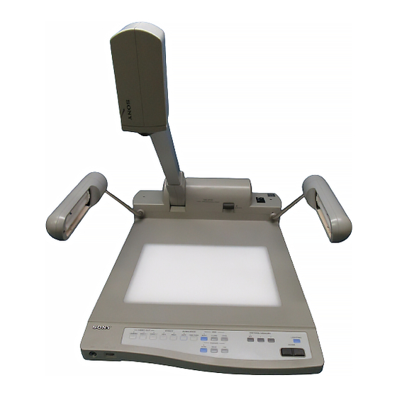
Sony VID-P110 Service Manual
Video presentation stand
Hide thumbs
Also See for VID-P110:
- Features & specifications (2 pages) ,
- Operating instructions manual (56 pages)
Table of Contents
Advertisement
Quick Links
Advertisement
Table of Contents

Related Manuals for Sony VID-P110


Summary of Contents for Sony VID-P110
- Page 1 VIDEO PRESENTATION STAND VID-P110 SERVICE MANUAL 1st Edition...
- Page 2 ! WARNING This manual is intended for qualified service personnel only. To reduce the risk of electric shock, fire or injury, do not perform any servicing other than that contained in the operating instructions unless you are qualified to do so.
-
Page 4: Table Of Contents
3-1-6. Adjustment Parts Location of VSW-60 Board ......... 3-5 (E) 3-2. Mechanism Adjustment (Right Position Adjustment of Camera) ........... 3-6 (E) 4. SEMICONDUCTOR PIN ASSIGNMENTS SEMICONDUCTOR INDEX ................. 4-1 DIODE ........................4-2 LED ........................4-2 TRANSISTOR ......................4-2 ........................4-3 VID-P110... - Page 5 5-4. Electrical Parts List ..................5-9 6. BLOCK DIAGRAMS VSW-60 ........................6-1 SY-248 ........................6-2 7. SCHEMATIC DIAGRAMS & BOARD LAYOUTS FRAME ........................7-1 VSW-60 ........................7-2 MA-87 ........................7-8 SY-248 ........................7-8 KSW-40 ......................... 7-10 PS-517 ........................7-12 PS-526 ........................7-14 VID-P110...
-
Page 7: Operating Instructions
3-864-452-11(1) Video Presentation Stand Operating Instructions Page 2 VID-P110 © 1998 by Sony Corporation... - Page 8 This equipment has been tested and found to comply with System Configuration .............6 Refer to them whenever you call upon your Sony dealer the limits for a Class A digital device, pursuant to Part 15 of Parts Identification ............8 regarding this product.
- Page 9 PAL model) pixels of the -inch CCD pickup device Various materials can be shot and the VID-P110 must first be installed. Refer to the allow 460 (for the NTSC model) or 450 (for the PAL displayed “Interface Manual” for details on the commands and model) horizontal resolution TV lines producing high communication protocol for this software.
- Page 10 When you connect video equipment such as a VCR or Note laserdisc player to this unit, you can switch the picture/ When you control the VID-P110 from a computer, Basic configuration sound to those from the connected video equipment, special software is required. To program in this The basic system for making a presentation or and vice versa by using the VIDEO OUT buttons.
- Page 11 Parts Identification For details on the use of each part, see the pages Rear Panel indicated in parentheses. For details on the use of the connectors, see pages 11 Camera and Operation Panel and 12. Camera VIDEO IN connectors 1,2 VIDEO OUT 2 connector (phono) (BNC type)
- Page 12 Open both arm lights until they fix in place. Precautions Connecting the Unit to Other Equipment • Unplug the VID-P110 from the wall outlet when it is Notes on connections not being used for a long period of time. To •...
- Page 13 After turning off the POWER switch, Note tighten the screw as shown below. When you control the VID-P110 from a computer, special software is required. To program in this The arm cannot stand upright. software, refer to the “Interface Manual”.
- Page 14 PATTERN MEMORY SET indicator does not light for about 2 seconds, the setting may not have Use the VOL control on the front of the VID-P110 to The VIDEO OUT buttons on the operation panel ZOOM been memorized.
- Page 15 Adjust the focus manually when you display: the material is not displayed naturally in the ONE • a material that includes small type or fine patterns PUSH mode. The VID-P110 unlock the white balance which are difficult to focus, setting and adjust the white balance automatically.
- Page 16 To shoot an PAL model Y: 1 Vp-p, 75 Ω, sync negative object far away from the VID-P110 itself, tilt up the Horizontal: 450 TV lines C: 0.286 Vp-p, 75 Ω camera and remove the close-up lens.
-
Page 17: Service Overview
1. Remove two screws “a” (B3x6). 2. Remove three screws “b” (B3x6) and then remove cover ass’y in the direction of arrow “B” while widenning the cover in the directions of arrow “A”s. Cover ass'y screw "a" (B3x8) screw "b" (B3x8) VID-P110 2-1 (E) -
Page 18: Removal Of Table Ass'y And Rear Panel Block
"b" (PTP3x10) Table ass'y hexagonal screw "c" screw (B3x10) CN501 Rear panel block screw "d" (B3x6) VSW-60 screw "c" board (B3x10) PS-526 board Light ass'y L Light ass'y R screw "a" screw "a" (PTP4x12) (PTP4x12) 2-2 (E) VID-P110... -
Page 19: Removal Of Main Parts
2. Remove the table ass’y. (Refer to section 2-1-2.) 3. Release harnesses from harness clamp and disconnect one connector (CN5) on PS-517 board. 4. Remove four screws (B3x10) and then remove back light ass’y. screw (B3x10) screw (B3x10) Back light ass'y PS-517 board Harness clamp VID-P110 2-3 (E) -
Page 20: Removal Of Drum Block And Light Ass'y L/R
"d" (PS3x6) screw "f" (PS3x6) Ground terminal washer screw "d" (PS3x6) VSW-60 board SY-248 board PS-517 board screw "f" (B3x10) screw "e" (P4x8) screw "c" (PWH4x10) screw "b" (K4x12) screw "c" screw "e" (PWH4x10) (P4x8) 2-4 (E) VID-P110... -
Page 21: Removal Of Ksw-40 Board
40 board. 5. Remove two screws (PS2x8) and then remove push switch (zoom). screw KSW-40 board (PS2x8) screw (PS2x8) Flexible Push switch card wire (Zoom) Flexible Flexible card wire card wire KSW-40 board nut (M2) Flexible card wire VID-P110 2-5 (E) -
Page 22: Removal Of Ma-87 Board
SY-248 board. 4. Disconnect three connectors (CN5, CN7, CN8) on SY-248 board. 5. Remove four screws (BVTP3x8) and then remove screw (BVTP3x8) MA-87 board SY-248 board. screw (BVTP3x8) CN801 screw (BVTP3x8) SY-248 board CN10 Flexible card wire 2-6 (E) VID-P110... -
Page 23: Removal Of Ps-517 Board
5. Remove three screws “b” (PWH3x6) and then remove PS-517 board. switching regulator. screw "a" screw "b" screw "a" (PWH3x6) (PWH3x6) (PWH3x6) Ground terminal screw "b" Ground terminal screw "b" (PWH3x6) screw "b" (PWH3x6) (PWH3x6) PS-517 board Switching regulator VID-P110 2-7 (E) -
Page 24: Removal Of Ps-526 Board/Ac Inlet/Ac Outlet (Uc Model Only)
And remove AC outlet in the direction of arrow. (BVTP3x8) VSW-60 board screw (BVTP3x8) claw (upper) claw (right) screw claw (left) (PWH3x6) screw AC outlet (PWH3x6) claw (lower) AC outlet (for UC) screw (B3x6) PS-526 board screw AC inlet (PWH3x6) 2-8 (E) VID-P110... -
Page 25: Removal Of Lampshade B
Lampshade C Lampshade claw connecting plate Socket Lampshade B Friction plate fixing plate Lampshade A screw (PTP2.6x8) Contact screw "b" (PTP3x10) Plyslider washer screw "a" (PTP2.6x6) Wave washer screw "a" Reflection plate (PTP2.6x6) Lamp holder Socket Fluorescent lamp VID-P110 2-9 (E) -
Page 26: Removal Of Lampshade C
5. Remove two screws “c” (PS2.6x5). After removing shade fixing plate, pull out the lamp arm. Lamp arm Shade fixing plate screw "b" (KTP2.6x8) screw "b" screw "c" (KTP2.6x8) (PS2.6x5) Escutcheon 6. Release two escutcheon claws, then remove lampshade claw claw Lampshade C 2-10 (E) VID-P110... -
Page 27: Replacement Of Camera Ass'y (Evi-370A/For Uc Model)
5. Remove four screws “a” (K2x3) and three screws “b” (P2x3), then remove the bracket from camera block. Step Bracket screw screw "b" (P2x3) connectors Step screw screw "a" (K2x3) screw "b" (P2x3) Camera block (EVI-370A) Front case screw screw (B2.6x6) (B2.6x6) VID-P110 2-11 (E) -
Page 28: Replacement Of Camera Ass'y (Evi-371A/For Ce Model)
5. Remove four screws “a” (K2x3) and three screws “b” (P2x3), then remove the bracket from camera block. Step Bracket screw screw "b" (P2x3) connectors Step screw screw "a" (K2x3) screw "b" (P2x3) Camera block (EVI-371A) Front case screw screw (B2.6x6) (B2.6x6) 2-12 (E) VID-P110... -
Page 29: Board Location
6 KSW-40 board 1 MA-87 board : MIC AMP 2 SY-248 board : SYSCON 3 VSW-60 board : VIDEO/AUDIO 4 PS-526 board : Power Input/Output, Filter 5 PS-517 board : Power Supply 6 KSW-40 board : Key Switch VID-P110 2-13 (E) -
Page 30: Connector I/O Signals (Video, Audio)
Power supply input x 1 : 120 V AC, 60 Hz (for UC model) 230 V AC, 50/60 Hz (for CE model) AC outlet x 1 (for UC model) : unswitched, maximum 2.5 A <external view> S-VIDEO Pin No. INPUT/OUTPUT signal Y (G) C (G) Y (X) C (X) S-VIDEO 2-14 (E) VID-P110... -
Page 31: Replacement Of Parts
(2) Standardization of Parts 4. Place new chip part in the desired position and solder Spare parts supplied from Sony Parts Center may not both ends. be always identical with the parts which actually in use due to “accommodating the improved parts and/or NOTE Do not use a chip part again once it has been engineering changes”... -
Page 33: Alignment
2. Cut the cable integument with a cutter. 3. Strip the cover of the shield wire with a nipper. 4. Check the Y/C core wire with a tester. 5. Connect alligator clips to each core wires. S-VIDEO Connector 1 GND (Y) 2 GND(C) VID-P110 3-1 (E) -
Page 34: Connection
. Connect Y signal from the signal Generator to CN1-2 pin (G-1) on side A of VSW-60 board. . Connect GND (Y) signal from the signal Generator to CN1-2 pin (G-1) on side A of VSW-60 board. 3-2 (E) VID-P110... -
Page 35: Negative Positive Invert Phase Adjustment
RED bright spots are on the axial R ± 3d 100% origin • After adjustment is completed, disconnect the S-VIDEO signal cable and connect the CN1. RED bright spots are on the axial R ± 3d • Turn the POWER switch OFF. VID-P110 3-3 (E) -
Page 36: Y/C Separation Adjustment
A=700± 14 mV p-p Step 2 1 CT301/VSW-60 (F1 on side A) TP301/VSW-60 (F2 on side B) Oscilloscope NTSC Minimize the A level (chroma). (A < 50 mV) Minimize the A level (chroma). (A < 50 mV) 3-4 (E) VID-P110... -
Page 37: Adjustment Parts Location Of Vsw-60 Board
3-1-6. Adjustment Parts Location of VSW-60 Board VSW-60 BOARD (side A) RV301 CT301 RV201 RV301 CT301 RV201 VSW-60 BOARD (side B) TP301 E501 VID-P110 3-5 (E) -
Page 38: Mechanism Adjustment (Right Position Adjustment Of Camera)
The camera is tilted and the left side of the table Step screw appears on the monitor screen. 4. Tighten the two step screws loosen at step 3 at the position that the right or left shift of the backlight frame on the table is eliminated. Camera 3-6 (E) VID-P110... - Page 39 S-80743AL-A7-S ......... 4-8 GL3PR8 ..........4-2 S-80743AL-A7-T1 ....... 4-8 SEL5620C-TP15 ......... 4-2 SN74HC02ANS ........4-8 SN74HC02ANS-E05 ......4-8 SN74HC04ANS ........4-8 SN74HC04ANS-E05 ......4-8 TC74HC221AF ........4-8 TC74HC221AF(EL) ......4-8 UPC1093T .......... 4-8 UPC1093T-E1 ........4-8 UPC4558G2 ........4-7 VID-P110...
-
Page 40: Diode
1SS119 1SS119-25TD DC008-02 IL00 TM001-02 IL00 -TOP VIEW- ***** ***** 1SR154-400TE-25 1SS355TE-17 2SC2334-L DC008-01 IL00 -TOP VIEW- ***** MA728 MA728-TX TYPE NO. PRINTED 2SC2785TP-HFE RD11ES-B2 RD11ES-T2B2 TC001-02 RD15ES-B2 IL00 RD15ES-T2B2 -TOP VIEW- ***** RD6.2ES-B2 2SC4177-L RD6.2ES-T1B 2SC4177-T1L5L6 RD6.8ES-B2 RD6.8ES-T2B2 VID-P110... - Page 41 PF0 - PF6 PRESCALER/ 32 kHz TIME BASE TIMER TIMER/COUNTER 68 - 71, 74 - 77 PG0 - PG7 8-BIT TIMER/COUNTER 0 22 - 29 PE0/ PH0 - PH7 8-BIT TIMER 1 PE5/TO 60 - 67 PI0 - PI7 PE5/ADJ VID-P110...
- Page 42 CXD1217M(SONY)FLAT PACKAGE CXD1217M-TH CXD1217M ( 3/5 ) C-MOS SYNC GENERATOR -TOP VIEW- ( NTSC,PALM ) FIELD1 4fsc IN 4fsc OUT FIELD2 EVEN SYNC OUT (+ 5V ) FIELD3 FIELD4 OFLD1 EVEN CL IN CL OUT H COM OBF/COLB OFLD 1...
- Page 43 PH0 - PH7 SERIAL INTERFACE UNIT PRESCALER/ 32 kHz (CH2) TIME BASE TIMER TIMER/COUNTER SCK2 60 - 67 PI0 - PI7 8-BIT TIMER/COUNTER 0 8-BIT TIMER 1 16-BIT CAPTURE CINT TIMER/COUNTER 2 SCL0 SCL1 C BUS INTERFACE UNIT SDA0 SDA1 VID-P110...
- Page 44 (+2 V to +6 V) OPEN RS-232 OUTPUT TTL/CMOS INPUTS 400k RS-232 OUTPUT OPEN RS-232 INPUT TTL/CMOS OUTPUTS RS-232 INPUT OPEN – V = +3 V to +12 V < CONTROL INPUTS SELECT ON CHANNEL LOW LEVEL HIGH LEVEL OPEN DON'T CARE VID-P110...
- Page 45 : CHROMA SIGNAL POSITIVE VOLTAGE REGULATOR : CHARACTER —FRONT VIEW— MUTE : MUTING : CHARACTER : Y SIGNAL OUTPUT MUTE : COMPOSITE SIGNAL INPUT OUTPUT COMMON CLAMP INPUT COMMON OUTPUT 6 dB 6 dB REFERENCE BIAS VOLTAGE CIRCUIT MUTE VID-P110...
- Page 46 74LCX SN74HC04ANS(TI)FLAT PACKAGE SN74HC04ANS-E05 C-MOS HEX INVERTERS -TOP VIEW- Y = A 0 ; LOW LEVEL 1 ; HIGH LEVEL NOTE: TYPE +2 to +5.5V 74AC/74VHC/74VHCT 74ACT/74HCT +4.5 to +5.5V 74LCX +2 to +3.6V OTHER TYPE +2 to +6V VID-P110...
-
Page 47: Spare Parts
Therefore, specified parts should be used in the case of replacement. (2) Standardization of Parts Repair parts supplied from Sony Parts Center may not be always identical with the parts which actually in use due to “accommodating the improved parts and/or engineering changes”... -
Page 48: Exploded View
3-447-073-00 s SPRING, TENSION ! 1-580-375-11 s INLET 3P 3-682-930-00 o LEG, RUBBER (ROUND) 1-671-130-11 o PRINTED CIRCUIT BOARD, PS-526 3-724-511-02 o SHOE, ACCESSORY 2-251-642-01 o GUARD, POWER SWITCH (for J, UC) 4-604-107-11 o GUARD, POWER SWITCH (for CE) VID-P110... -
Page 49: Printed Circuit Boards
3-186-640-01 o PLATE, SHIELD, MICROPHONE (A) 1-543-993-11 s CORE, FERRITE (for CE) 3-688-814-11 s CAP, SWITCH ! 1-570-117-51 s SWITCH, POWER 4-053-463-01 o HOLDER (S), CORE (for CE) 1-692-257-11 s SWITCH, PUSH (ZOOM) 1-769-207-11 o WIRE, FLAT TYPE (FFC•CONNECTOR) VID-P110... -
Page 50: Drum
3-186-518-01 o RING, CLICK 3-187-378-01 o BRACKET, BRAKE 3-186-519-01 o COVER, ARM 3-187-379-02 s SHOE, BRAKE 3-186-624-01 o SPRING (for J, UC) 3-437-288-00 o SPRING, TENSION 3-201-467-01 o SPRING (4), LOW WEIGHTING (for CE) 3-723-749-01 o BUSHING, SNAP 3-186-790-01 o STOPPER VID-P110... -
Page 51: Camera Block
3-186-635-01 s LENS, CLOSE UP 3-200-596-01 o SPACER, CAMERA FIXED 3-186-637-01 o SCREW, FITTING 3-613-164-00 o SHAFT, STEP 3-188-679-01 s SHOE, BRAKE (A) A-8321-711-A s CAMERA ASSY (N) 3-188-682-01 o JOINT (A) A-8321-749-A s CAMERA ASSY (P) 3-188-683-01 o JOINT (B) VID-P110... -
Page 52: Lighting (Left) Block
3-187-341-01 o PLATE, FRICTION 3-176-690-01 o SHOE (LOWER), BRAKE 3-187-342-01 o PLATE, FIXED, SOCKET 3-176-692-01 o SUPPORT, BRAKE 3-200-823-01 o SPRING (A), GROUND 3-186-531-01 o LAMP SHADE A 3-701-448-21 s WASHER, 12 3-186-532-01 o LAMP SHADE B 3-186-533-01 o LAMP SHADE C VID-P110... -
Page 53: Lighting (Right) Block
3-187-341-01 o PLATE, FRICTION 3-176-690-01 o SHOE (LOWER), BRAKE 3-187-342-01 o PLATE, FIXED, SOCKET 3-176-692-01 o SUPPORT, BRAKE 3-200-824-01 o SPRING (B), GROUND 3-186-531-01 o LAMP SHADE A 3-701-448-21 s WASHER, 12 3-186-532-01 o LAMP SHADE B 3-186-533-01 o LAMP SHADE C VID-P110... -
Page 54: Packing Materials And Accessories
! 1-782-929-11 s CORD, POWER SUPPLY (BS 3P) (for CE) 3-200-888-01 s INDIVIDUAL CARTON 3-864-451-01 s MANUAL, INTERFACE (for J) 3-864-451-11 s MANUAL, INTERFACE (for UC, CE) 3-864-452-01 s MANUAL, INSTRUCTION (for J) 3-864-452-11 s MANUAL, INSTRUCTION (for UC, CE) VID-P110... -
Page 55: Electrical Parts List
J MODEL:S/N 10,121 AND HIGHER UC MODEL:S/N 71,082 AND HIGHER 1-570-969-11 s SWITCH,KEY BOARD CED MODEL:S/N 50,301 AND HIGHER 1-570-969-11 s SWITCH,KEY BOARD 1-570-969-11 s SWITCH,KEY BOARD 1-570-969-11 s SWITCH,KEY BOARD 1-570-969-11 s SWITCH,KEY BOARD 1-570-969-11 s SWITCH,KEY BOARD 1-570-969-11 s SWITCH,KEY BOARD VID-P110... - Page 56 1-564-005-11 o PIN,CONNECTOR 6P 1-564-507-11 o PLUG,CONNECTOR 4P 1-691-960-21 o PIN,CONNECTOR(PC BOARD) 3P 1-691-960-21 o PIN,CONNECTOR(PC BOARD) 3P 8-719-200-82 s DIODE 11ES-B2 8-719-200-82 s DIODE 11ES-B2 8-719-110-22 s DIODE RD11ES-B2 8-719-109-97 s DIODE RD6.8ES-B2 8-719-200-82 s DIODE 11ES-B2 5-10 VID-P110...
- Page 57 8-759-042-02 s IC S-80743AL-A7 8-759-433-52 s IC AT24C01A-10SC-#B 8-759-925-74 s IC SN74HC04ANS IC10 8-752-899-00 s IC CXP84412-007Q 8-729-028-92 s TRANSISTOR DTA144TUA-T106 8-729-028-92 s TRANSISTOR DTA144TUA-T106 8-729-028-92 s TRANSISTOR DTA144TUA-T106 8-729-028-92 s TRANSISTOR DTA144TUA-T106 8-729-028-92 s TRANSISTOR DTA144TUA-T106 8-729-028-92 s TRANSISTOR DTA144TUA-T106 VID-P110 5-11...
- Page 58 1-216-073-00 s RES,CHIP 10K 5% 1/10W R137 1-216-073-00 s RES,CHIP 10K 5% 1/10W 1-216-073-00 s RES,CHIP 10K 5% 1/10W R138 1-216-073-00 s RES,CHIP 10K 5% 1/10W 1-216-073-00 s RES,CHIP 10K 5% 1/10W R139 1-216-073-00 s RES,CHIP 10K 5% 1/10W 5-12 VID-P110...
- Page 59 1-163-091-00 s CERAMIC,CHIP 8pF 0.25pF 50V C120 1-163-091-00 s CERAMIC,CHIP 8pF 0.25pF 50V C121 1-165-319-11 s CERAMIC.CHIP 0.1uF C122 1-117-681-11 s ELECT,CHIP 100uF 20% 16V C123 1-163-133-00 s CERAMIC,CHIP 470pF 5% 50V C124 1-163-021-91 s CERAMIC,CHIP 0.01uF 10% 50V VID-P110 5-13...
- Page 60 8-719-064-61 s DIODE 01BZA8.2(TE85L) D507 8-719-064-61 s DIODE 01BZA8.2(TE85L) C434 1-117-681-11 s ELECT,CHIP 100uF 20% 16V D509 8-719-064-61 s DIODE 01BZA8.2(TE85L) C435 1-163-021-91 s CERAMIC,CHIP 0.01uF 10% 50V D511 8-719-064-61 s DIODE 01BZA8.2(TE85L) C436 1-163-133-00 s CERAMIC,CHIP 470pF 5% 50V 5-14 VID-P110...
- Page 61 Q104 8-729-117-32 s TRANSISTOR 2SC4177-L6 1-216-025-91 s RES,CHIP 100 55 1/10W Q105 8-729-117-32 s TRANSISTOR 2SC4177-L6 1-216-097-91 s RES,CHIP 100K 5% 1/10W Q106 8-729-117-32 s TRANSISTOR 2SC4177-L6 Q107 8-729-117-32 s TRANSISTOR 2SC4177-L6 1-216-073-00 s RES,CHIP 10K 5% 1/10W VID-P110 5-15...
- Page 62 1-216-037-00 s RES,CHIP 330 5% 1/10W R142 1-216-306-11 s RES,CHIP 3.9 5% 1/10W (FOR J,UC MODEL ONLY) R143 1-216-306-11 s RES,CHIP 3.9 5% 1/10W 1-216-032-00 s RES,CHIP 220 5% 1/10W R144 1-216-295-91 s SHORT (FOR CED MODEL ONLY) 5-16 VID-P110...
- Page 63 1-562-506-11 o CONNECTOR,MICRO(HOUSING) 4P 2pcs 1-562-505-11 o CONNECTOR,MICRO(HOUSING) 3P 8pcs 1-562-490-11 o CONTACT,MICRO(SMALL TYPE) AWG22-30 HARNESS,SUB(PS-EVI)(J,UC MODEL ONLY) CN2/PS-517 Board to CN301/EVI 1-569-195-11 o HOUSING,CONNECTOR 2P 1-569-617-11 o HOUSING,CONNECTOR 2P 2pcs 1-766-387-11 o TERMINAL,SOLDERLESS AWG26-28 2pcs 1-569-193-11 o TERMINAL,SOLDERLESS AWG24-30 VID-P110 5-17...
-
Page 65: Block Diagrams
C IN IC103(2/3) Q210 Y IN Q101-106 BUFFER Y-GAMMA COMPENSATE IC102 IC101(2/2) Q108,109 Q110 IC103(1/3) Q107 Q112 BUFFER BUFFER BUFFER BUFFER IC107(2/2) IC101(1/2) Q111 OBLK BUFFER IC106 SYNC IC104 GENERATER C SYNC SYNC IC105 OBLK SEPARATE V SYNC VSW-60 X101 VID-P110... - Page 66 INT1 RS-232C IC9(3/7)(4/7),Q13,Q14 DRIVER/RECEIVER SCK0 SCK1 ECCP ECCP DC ECCP SIG DRIVER/RECEIVER ECCP SIG MAIN VID-P110/VID-P150 SELECT LIGHTING PB7,PB6 ARM LIGHT ON/OFF BACK LIGHT ON/OFF +12V E PROM AUDIO OFF L; AUDIO OFF L; CAMERA VIDEO 1/L; VIDEO 2 PH5-PH6 VIDEO OUT L;...
- Page 67 C OUT C OUT L:CAMERA L:CAMERA L:AUDIO OFF L:AUDIO OFF Y OUT Y OUT RS-232C ECCP DC C IN ECCP SIG ECCP GND J,UC MODEL CED MODEL Y IN AUDIO +9 V MIC IN MA-87 J801 CN801 FRAME MIC OUT VID-P110...
-
Page 68: Vsw-60
V-SEL MUTE IC4(6/6) CL11 CL12 CL13 CL10 SN74HC04ANS-E05 470p 0.01 IC4(1/6) SN74HC04ANS-E05 NEGA IC4(2/6) L;NEGA SN74HC04ANS-E05 L;B&W SY-248 VIDEO1/L;VIDEO2 IC4(3/6) Board L;CAMERA SN74HC04ANS-E05 L;VIDEO1/VIDEO2 L;AUDIO OFF IC4(4/6) IC4(5/6) SN74HC04ANS-E05 V1-S-ON V2-S-ON SN74HC04ANS-E05 VSW-60 (1/5) CAMERA CL26 CL27 L;S1 L;S2 VID-P110... -
Page 69: Vsw-60
OBLK R132 MODE1 OSYNC 2.2k RSET BURST/BACK MODE2 C123 C124 470p 0.01 TEST C125 R134 R135 O2FH C127 C126 R133 680k R136 4.7k R140 R141 C128 REF NO. J.UC R145 NO M'T 0 Ω VSW-60 (2/5) X101 14.318 14.1875 VID-P110... - Page 70 R220 C205 R205 2SA1611T1-M5M6 R218 2.2k R221 R203 R210 Q204 R216 C211 2.2k 2.7k 2SA1611T1-M5M6 POSI-C C210 CL202 NEGA BURST PHASE POSI C IC103(2/3) MC74HC4053F-T2 B/W-C Q210 2SC4177-T1L5L6 CL203 R222 2.2k B/W C C212 R223 2.2k VSW-60 (3/5) OBLK VID-P110...
- Page 71 V SAG 2 470p 0.01 MUTE V OUT 1 V OUT 2 C459 C422 R416 R417 10 16V CAMERA MONITOR C463 V-GND E401 1,2,3,5 1,2,3,5 VIDEO GND VSW-60 (4/5) NOTE) 'NM:NO MOUNT REF NO. J.UC R415 Ω Ω R417 Ω Ω VID-P110...
- Page 72 AUDIO GND AUDIO +9V VIDEO +9V CL501 CL502 E501 TP501 D515 (TO PS-517 Board) 1SS355TE-17 CN501 TP502 CL503 IC501 D516 NJM7805FA 1SR154-400-TE25 1,2,3,4 C501 C503 C505 C506 C507 C504 C508 AUDIO GND VIDEO GND 1,2,3,4 VSW-60 (5/5) NOTE) 'NM:NO MOUNT VID-P110...
- Page 73 Q204 Q205 Q206 Q207 Q208 Q209 Q210 Q301 Q302 Q303 Q304 FL10 Q305 FL11 Q306 FL12 FL13 RV201 FL501 RV301 FL502 FL503 TP301 FL504 TP302 FL505 TP501 FL506 TP502 FL507 X101 VSW-60 - B SIDE - SUFFIX : -11 VID-P110...
- Page 74 1000p 3.3k R802 IC801(2/2) 100k NJM4558DD * RV801 MIC VOLUME J MODEL 10,001 10,120 10,121 UC MODEL 70,001 71,081 71,082 CED MODEL 50,001 MA-87 SY-248 - B SIDE - SUFFIX : -12 IC10 CN10 FB11 FL10 FL11 FL12 FL13 VID-P110...
- Page 75 SWITCH 2 SN74HC04ANS-E05 R161 100k 100k 100k 100k SWITCH 3 FL11 SWITCH 4 FL12 SWITCH 5 FL13 SWITCH 6 ZOOM SWITCH GL3PR8 2.2k R114 R160 GL3PR8 2.2k SY-248 R115 R112 R113 100k 100k 100k 100k 100k 100k EXTAL XTAL 9.8304MHz VID-P110...
- Page 76 AUTO NEAR 1SS119-25TG SEL5620C-TP15 B&W NEGA SEL5620C-TP15 SEL5620C-TP15 AUTO W.BALANCE W.BALANCE B&W NEGA LIGHTING AUTO ONE PUSH 1SS119-25TG CL17 CL18 CL19 CL20 CL21 6.8k WIDE SLOW WIDE FAST 3.9k TELE SLOW TELE FAST ZOOM SW RD6.2ES-T2B2 KSW-40 7-10 7-10 VID-P110...
-
Page 77: Ksw-40
KSW-40 KSW-40 KSW-40 - A SIDE - SUFFIX : -11 KSW-40 - B SIDE - SUFFIX : -11 VID-P110 7-11 7-11... - Page 78 PS-517 PS-517 PS-517 PS-517 - A SIDE - - B SIDE - SUFFIX : -11 SUFFIX : -11 7-12 7-12 VID-P110...
- Page 79 ARM LIGHT (H) 1000p 4.7k ARM LIGHT (S) 2SC2334-L 0.15 4700p 630V CL17 0.033 2.2k 1000p 4.7k 400V TO ARM LIGHT(R) 4700p 4700p 4.7k CL18 4700p ARM LIGHT (H) ARM LIGHT (S) 1000p 2SC2785TP-HFE 11ES2-TA2B 11ES2-TA2B 2SC2334-L PS-517 VID-P110 7-13 7-13...
- Page 80 AC OUT ; PS-526 MAX 300W 1-671-130-12 (J/UC MODEL) J MODEL:10,121 AND HIGHER UC MODEL:71,031 AND HIGHER CED MODEL:50,001 AND HIGHER PS-526 PS-526 PS-526 - A SIDE - - B SIDE - SUFFIX : -12 SUFFIX : -12 7-14 7-14 VID-P110...
- Page 81 AC The material contained in this manual consists of leakage. Check leakage as described below. information that is the property of Sony Corporation and is intended solely for use by the purchasers of the LEAKAGE TEST equipment described in this manual.
- Page 82 Printed in Japan Sony Corporation 1998. 11 04 VID-P110 (J, UC, CE) J, E Broadcasting & Professional Systems Company 9-955-161-01 ©1998...
Need help?
Do you have a question about the VID-P110 and is the answer not in the manual?
Questions and answers