
Related Manuals for SATO KEIRYOKI 7790-00


Summary of Contents for SATO KEIRYOKI 7790-00
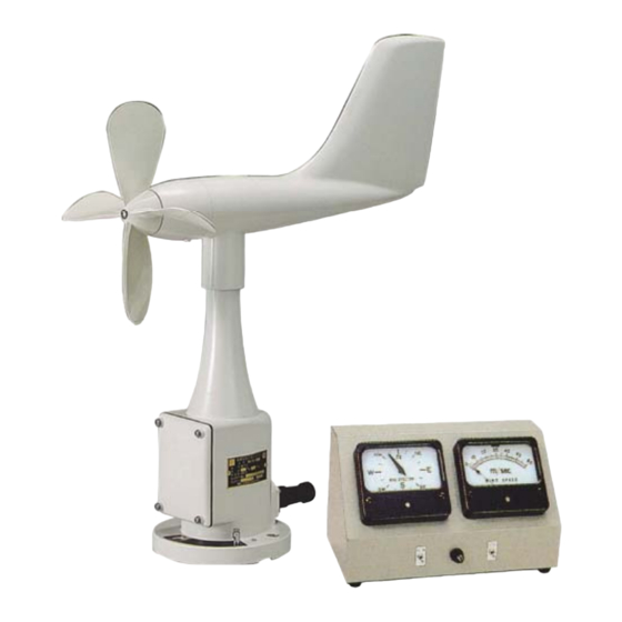
- Page 1 Instruction Manual No. 7790-00 Wind Speed and Direction Indicator (Scale range: 2 to 70 m/s, 16 cardinal points) 3-4, Kanda-kajicho, Chiyoda-ku, Tokyo 101-0045 Japan URL: http://www.sksato.co.jp/english/ EW-J15004...
- Page 2 Description This is an instrument for measuring and monitoring instantaneous speed and direction of the wind by connecting the sensor and the indicator with a cable. Install the wind speed and direction sensor on top to a steel pole for observation. Standard Components 1) Airplane type wind speed and direction sensor 1 pc.
- Page 3 Measuring Principles 1. Sensor 1) Wind speed A wind speed sensor generates alternating current which is proportional to wind speed and output. 2) Wind direction The turning angle of the counterbalanced tail is relayed to the axis of synchro-motor inside the sensor and converted to electrical signals.
- Page 4 3. Cable between Sensor and Indicator 1) Cable of 7 wires of at least 0.75 mm is usable for maximum 2 km in length for one-indicator, 1 km for two-indicators. 2) If induction by radio waves occurs, use shielded cable and earth end of the shield (E3). 3) Set the units and the cable away from powerful transmitting antennas as well as high-voltage and large-current circuits.
- Page 5 Maintenance The sensor can be used for a long period of time without being oiled or greased, but please check the followings at least once a year. 1. The Sensor Unit 1) When the wind is calm (less than 2 m/s), check if the movement of propeller and tail is smooth or not.
- Page 6 2. The reading shown by the indicator is lower than the actual wind speed. 1) One or two bridges of the rectifier in the indicator have failed. (often caused by lightning). 2) A cable is not connected properly. a. Re-tighten the screws on the terminal block. b.
- Page 7 4. When the power is turned on for the first time after installation or after reconnecting the cables, the pointer of indicator turns in the opposite direction to the tail of the sensor unit or turns 180° off. 1) If two of terminals 3, 4 or 5 (at the second winding of synchro-motor) are transposed, the pointer will reverse.
- Page 8 B. Wind Direction Section 1. Check the following procedures for malfunction of the synchro-motor inside the sensor. 1) After turning off power of the indicator, take off the wires connected to the sensor terminals No. 3, 4, 5 and 6. 2) Check the resistance value between terminals with a tester.
- Page 9 How to install the propeller of Wind & direction Sensor 1) Put the each flat surface of the axis and the axis hole of propeller together and fix the propeller with the shaft. 2) Secure the propeller fixing screw into the shaft after fully turning lock screws. Tightening torque: 14kg・cm to18kg・cm.
-
Page 10: Wind Speed And Direction Sensor
Lid of terminal box Polycarbonate resin 5 Propeller Polycarbonate resin 4 Grand PBT resin 3 Stand Polycarbonate resin 2 Body Polycarbonate resin 1 Tail Glass + polyester resin No Name Materials WIND SPEED AND DIRECTION SENSOR 7790-00 8 0 0 -0 7 8... - Page 11 Switch for wind speed Fuse holder Power switch Ventilation hole (rear) Rubber feet Terminal (M3 screw) Indicator...
-
Page 12: Surge Absorber
23- 008 brush and ( 929- 162) slip ring terminal block generator yellow 1 1 1 propeller Z1 orange 2 2 2 terminal block tail 3 3 3 S2 Z2 yellow yellow 4 4 4 Synchro-motor S3 blue Z3 blue 5... - Page 13 930-201 Wind speed and direction sensor G P SM EARTH 1 4 5 6 7 2 3 8 Use shield cable if induction by radio waves occur 220VAC 7 8 2 1 2 3 4 5 6 8 U V Z2...
Need help?
Do you have a question about the 7790-00 and is the answer not in the manual?
Questions and answers