Table of Contents
Advertisement
Quick Links
Advertisement
Table of Contents

Subscribe to Our Youtube Channel
Related Manuals for GKD 1 L Series


Summary of Contents for GKD 1 L Series
- Page 1 TOTAL MOMENT INDICATOR INSTALLATION MANUAL COPYRIGHT NOTICE Intended audience: This document contains sensitive information. It may not be shared with other parties without the express written permission of GKD Technologies Ltd. M1000002 V1.2 - 11/2021...
-
Page 2: Table Of Contents
CONTENTS Page INTRODUCTION System Layout 2 COMPONENT IDENTIFICATION Series 1-L Display Angle Sensor Pressure Transducer CAN to USB Interface 3 INSTALLATION Series 1-L Display Angle Sensor Pressure Transducer Alarm 4 SERIES 1-L GENERAL INFORMATION & WIRING (TYPE 1) Alarm 5 SERIES 1-L GENERAL INFORMATION & WIRING TYPE 2) Alarm 6 CAN BUS AND PRESSURE SENSOR WIRING CAN Bus... - Page 3 Stage 3 - Data Logger On/Off Control Stage 4 - Set Maximum Moment Verification 10 PC SETUP AND MONITOR 10.1 PC Connection 10.2 PC Indicator Monitoring 10.3 PC Advanced User 10.4 Calibrate Screen APPENDIX - GKD USB DRIVER INSTALLATION www.gkdtechnologies.com M1000002 V1.2 - 11/2021...
-
Page 4: Introduction
INTRODUCTION This manual contains the installation and set-up instructions for the Series 1-L Total Moment Indicator. Installation should only be carried out by competent and trained staff as this product is a safety product. During installation it is assumed that industry standards will be observed and all cabling will be protected against damage either from the movement of the machine or from collisions that may occur during normal operations (trees &... -
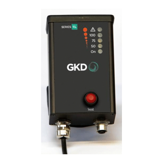
Page 5: Component Identification
A USB to CAN Converter Interface is used to allow a PC to communicate with the Series 1-L during initial set-up and for later monitoring purposes. IMPORTANT NOTE: ENSURE USB DRIVERS ARE INSTALLED FOR THE USB TO CAN CONVERTER. SEE GKD USB DRIVER INSTALLATION NOTICE! www.gkdtechnologies.com... -
Page 6: Installation
3 INSTALLATION Series 1-L Display The back of the display is fitted with a ball-joint mount. The joint base should be secured with 2 x M5 bolts on fixing holes at 48.5mm spacing, and can be mounted on a horizontal, angled, or vertical surface as appropriate. -
Page 7: Pressure Transducer
Pressure Sensor Pressure sensors use a G1/4 hydraulic interface to the machine hydraulics. The ram full side pressure transducer, and the optional reverse side (rod side) pressure transducer, must measure the pressure in the lift ram at all times. Therefore, the measuring point must be on the ram side of any hose burst check valves that may be fitted. -
Page 8: Series 1-L General Information & Wiring (Type 1)
Solenoid Duty Input Alarm function is off if the 1TMI is unpowered, in a Fault state, or in a Angle load-limited state. Sensor M12 CAN Cable Pressure Transducer M1000002 GKD Technik Ltd www.gkdtechnologies.com M1000002 V1.2 - 11/2021... -
Page 9: Series 1-L General Information & Wiring Type 2)
1TMI is M12 CAN Cable Angle unpowered, in a Fault state, or Sensor in a load-limited state. A = Full Side Data Logger B = Rod Side (Optional) M1000002 GKD Technik Ltd www.gkdtechnologies.com M1000002 V1.2 - 11/2021... -
Page 10: Can Bus And Pressure Sensor Wiring
6 CAN BUS AND PRESSURE SENSOR WIRING CAN Bus The CAN bus connections are as follows: CAN Lo +V Supply 0V (Ground) CAN High CAN Bus M12 Connector Pin 1 - Brown Pin 2 - White Pin 3 - Blue Pin 4 - Black The angle sensor and display connect to a CAN bus. -
Page 11: Initial Setup
7 INITIAL SETUP When all of the components have been installed then the system is ready for Calibration. Diagrams below show typical measurements for Stub with pulling Ram. If boom CAN be set to zero Ram Stub Pin Stub Boom Pin Angle Sensor Max Angle If boom CANNOT be set to zero... -
Page 12: Machine Dimensions With Boom Ram Pulling From Above The Stub Boom Pin
Angle Sensor M12 connection is still made during the set-up and calibration process. IMPORTANT NOTE: ENSURE USB DRIVERS ARE INSTALLED FOR THE USB TO CAN CONVERTER. SEE APPENDIX - GKD USB DRIVER INSTALLATION NOTE. Apply power to the Series 1-L System. www.gkdtechnologies.com M1000002 V1.2 - 11/2021... -
Page 13: Pc Connection And Software
On a laptop PC create a new directory named with the Machine Type/Serial Number of the crane on which the Series 1-L system is to be installed. Copy the latest GKD Series 1-L PC software supplied (e.g. GKD1TMI2.xx.exe) into the new directory and double click on that file to run the software. -
Page 14: Calibration
9 CALIBRATION Set up & Calibration of the Series 1-L is achieved in 4 stages: 1) Zero Angle sensor setting (75% LED Lit in Calibrate mode). 2) Zero Pressure sensor setting for no-load condition (100% LED Lit in Calibrate mode). 3) Data logger function On or Off control (75 &... -
Page 15: Stage 2 - Zero Pressure Sensor
9 CALIBRATION (CONT.) Stage 2 - Zero Pressure Sensor With No Load and the machine set to the minimum radius combination of the boom, dipper or any extending boom fitted, the hydraulic ram pressure will be at the minimum value supporting the weight of the boom etc. -
Page 16: Stage 4 - Set Maximum Moment
9 CALIBRATION (CONT.) Stage 4 - Set Maximum Moment With the machine set to the maximum radius combination of the boom, dipper or any extending boom fitted, and apply the maximum load rated for that machine at the maximum radius position. This represents the Maximum Moment allowed. Ensure the magnet is fitted on the top of the display as shown on page 14. -
Page 17: Pc Setup And Monitor
10 PC SETUP & MONITOR The PC software is used to enter the initial machine data, X1, X2 etc. but can also be used to monitor the condition of the machine, store the calibration settings and even adjust the calibration settings as required. 10.1 PC Connection The machine data etc. -
Page 18: Pc Advanced User
10 PC SETUP & MONITOR (CONT.) 10.3 PC Advanced User In the Indicator screen, enter the Password 861961. The central Calibrate box now becomes active (not greyed out). Click the Calibrate box and enter the Calibrate screen. 10.4 Calibrate Screen In the Calibrate screen, click “Receive Settings”... -
Page 19: Appendix - Gkd Usb Driver Installation
The GKD USB to CAN Converter includes an FTDI USB interface chip and a special Windows driver is needed to allow the GKD Series 1-L PC software to use a USB port to talk to the Series 1-L Display Unit. This note details how the driver software can be installed. - Page 20 DISCLAIMER Incorrect installation of any part and or incomplete calibration will affect the correct operation of the Series 1-L. If in doubt contact GKD Technologies. GKD Technologies reserve the right to change these instructions in line with the policy of continuous improvement.
Need help?
Do you have a question about the 1 L Series and is the answer not in the manual?
Questions and answers