MinXray HF100H Service Manual
Hide thumbs
Also See for HF100H:
- Service manual (42 pages) ,
- Installation and operating instructions manual (23 pages) ,
- Service manual (36 pages)
Advertisement
Quick Links
This manual is established for repair・adjustment of the MinXray model
unit. Copy and transfer without notice is prohibited.
Section
1.0
2.0
3.0
4.0
5.0
6.0
7.0
8.0
9.0
10.0
11.0
12.0
13.0
14.0
15.0
16.0
17.0
HF100H
SERVICE MANUAL
Contents
Introduction
Device history
Specifications
Operating procedures
Pre-adjustment
Re-adjustment of kV
Re-adjustment of pre-heat time and mA
Re-adjustment of exposure time
Sample of output waveform
Pre-adjustment mA with/without HF Tester
Measure mA by mA jack output
Wiring diagram
Schematic diagram
Trouble - shooting guide
Parts list
Advantech Model R72/32 operator's
installer's manual
Collimax Collimator operator's installer's manual
10 September 2003
HF100H
portable x-ray
Page
1
2
3
5
7
11
13
16
17
18
20
21
22
28
32
Appendix 1
Appendix 2
Advertisement

Related Manuals for MinXray HF100H


Summary of Contents for MinXray HF100H
- Page 1 10 September 2003 HF100H SERVICE MANUAL HF100H This manual is established for repair・adjustment of the MinXray model portable x-ray unit. Copy and transfer without notice is prohibited. Section Contents Page Introduction Device history Specifications Operating procedures Pre-adjustment Re-adjustment of kV...
- Page 2 MinXray, Inc., its agents and representatives, do not accept any responsibility for: Injury or danger to patient or other personnel from x-ray exposure or electrical shock.
-
Page 3: Device History
2.0 DEVICE HISTORY Item No. Contents Start S/No. Pre- production 19716 Solder lead on the insert 21192 Making 8 screws lock tighter for outer case 21545 Fixing the nut of PCB M9110 by bond (KE42) 23232 Using PCB M3107-B 23232 Adding the labels 23232 “... -
Page 4: Warm-Up Time
15A(100kV) Maximum voltage consumption -------- 3.5kVA ±10% NOTE : This unit would be severely damaged if it is used with incorrect line voltage. HF100H Check the rating label on the for the correct input voltage for each unit. OUTPUT :... -
Page 5: Exposure Switch
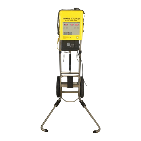
3.0 SPECIFICATIONS FILTRATION : inherent filtration 2.2mm Al collimator filtration 2.0mm Al total filtration 4.2mm Al WEIGHT : 20 kgs SIZE : 29 cm (W) × 23.8 cm (H) × 45.5 cm (L) POWER CORD : 3.6 m EXPOSURE SWITCH : two stage, 3.0 m Specifications subject to change without notice. - Page 6 Time increments are 0.01 sec. per step. mA SETTING : No adjustment. Factory set at 20 mA. SOURCE-IMAGE DISTANCE: HF100H Use the tape measure on the side of the to confirm that the x-ray unit is positioned at the correct source-image distance (SID) for the view being taken.
- Page 7 POWER OFF : When the POWER SWITCH is pressed, all indicators on the control panel are off. HF100H WARNING LAMP : has 2 kinds of warning lamps. If either of them is lit, x-ray cannot be generated. Each detail is as follows.
- Page 8 ※ Push in and pull out connectors only with MAIN POWER OFF. ↑ 12 V ↓ 10 mS ← → ※TIME BASE WAVEFORM NOTE : Please contact MinXray, Inc. ( Service Department ) for information about purchasing special test equipment (HF Tester).
- Page 9 5.0 Pre-adjustment REFFERENCE : There are three jumpers on M3108AH (10SEC ,TEST and LBD) 10SEC : When jumper is put in, WARM UP time is 1 sec. DO NOT USE. When jumper is pulled out, it is 10 sec. This jumper is for adjustment at the factory before shipment. So, please don’t use the device with jumper.
- Page 10 5.0 Pre-adjustment 5-5. M9111-1 PC Board adjustment This adjustment has to be done after connecting all connectors completely. Actual x-ray exposure is not necessary. ※Each PC Board delivered from the factory has been already adjusted. 1. Adjustment of VR3 (DC370V) Adjust voltage between 370 (+) and GND (–) to be 368.5 –...
- Page 11 5.0 Pre-adjustment 5-6. M9112 PC Board adjustment This adjustment has to be done after connecting all connectors completely. Actual x-ray exposure is not necessary. ※Each PC Board delivered from the factory has been already adjusted. 1. Adjustment of FQ1 Adjust frequency between FQ1 (+) and GND (–) to be 120 kHz by turning VR1. Turning clockwise increases frequency.
- Page 12 6.0 Re-adjustment of kV This adjustment has to be done after connecting all connectors completely. Actual exposure is necessary. NOTE : This adjustment requires that an exposure be made. Please observe all radiation related safety precautions. ※This adjustment should be done whenever Insert Box or Inverter PC Board (M9111-1 PCB) is replaced.
- Page 13 6.0 Re-adjustment of kV 6-1. Adjustment of 70 kV by VR4 Adjust the ch1 (Ep) by VR4 to be 3.4 V ±0.5 V. Turning clockwise increases kV. 6-2. Adjustment of 100 kV by VR4 Adjust the ch1 (Ep) by VR4 to be 4.9 V ±0.5 V. Turning clockwise increases kV.
- Page 14 7. 0 Re-adjustment of Pre-heat and mA This adjustment has to be done after connecting all connectors completely. Actual exposure is necessary. NOTE : This adjustment requires that an exposure be made. Please observe all radiation related safety precautions. *This adjustment should be done whenever Insert Box or Inverter PC Board (M9112 PCB) is replaced.
- Page 15 7. 0 Re-adjustment of Pre-heat and mA 7-1. Adjustment of Pre-heat time 1. Pre-heat time is short. Make Pre-heat time longer by turning VR3 counterclockwise. 2. Pre-heat time is long. Make Pre-heat time shorter by turning VR3 clockwise. 3. Pre-heat time is appropriate. ※Acceptable limit : 20 msec.
- Page 16 7. 0 Re-adjustment of Pre-heat and mA 7-2. Adjustment of mA by VR5 ※Adjust average of peak values of IP waveform to be 1.9 V by VR5.
- Page 17 8.0 Re-adjustment of exposure time This adjustment has to be done after connecting all connectors completely. Actual exposure is necessary. NOTE: This adjustment requires that an exposure be made. Please observe all radiation related safety precautions. Check the exposure time by using an external exposure time meter such as the VICTOREEN NERO.
- Page 18 9.0 Sample of output waveform Normal waveform 100 kV ・ 20 mA...
- Page 19 ※ The HF tester is a tool to inspect and adjust the control panel. It is specially manufactured and can be purchased only from MinXray, Inc. The upper control panel is removed from the body after four screws on the side of the body are removed.
- Page 20 10.0 Pre-adjustment mA with/without HF Tester 10-2 Pre-adjustment mA without HF Tester ※ Each PC Board delivered from the factory has already been adjusted. 1. M3108AH adjustment (Refer to page 8 ) kV adjustment : kV is decreased by turning VR1 clockwise. 1.
- Page 21 Jack ( Single round phone jack, 3.5 mm diameter) connection diagram 1. Close the collimator shutters fully. 2. Connect voltage measurement equipment (ex. Osilloscope) with mA jack (Single round phone HF100H jack, 3.5mm/dm ) to socket on the back of the 3. Make exposure.
-
Page 22: Wiring Diagram
12.0 Wiring Diagram -21-... - Page 23 13.0-1 Schematic Diagram PCB M3108AH -22-...
- Page 24 13.0-2 Schematic Diagram PCB M3107BH -23-...
- Page 25 13.0-3 Schematic Diagram PCB M9111-1 -24-...
- Page 26 13.0-4 Schematic Diagram PCB M9112 -25-...
-
Page 27: Schematic Diagram
13.0-5 Schematic Diagram PCB M3106B LED1 X-RAY X-RAY LED2 STAND BY STAND BY LED3 WARM UP WARM UP LED4 ERROR ERROR Buzzer BUZZER 12VDC -26-... - Page 28 13.0-6 Schematic Diagram PCB M9110 -27-...
- Page 33 COLLIMATOR TRANSFORMER (474-1002, for 120V) 10758 COLLIMATOR TRANSFORMER (474-1003. for 230V) 10750 POWER SUPPLY (SVB-24-SA, for 120V) 10699 POWER SUPPLY (SVB-24-SB, for 230V) 10752 PCB M3108AH (HF100H) 10585 SPACER (M3 X 10) 10895 PCB M3107BH (HF100H) 10841 Collar(8mm) 10703 PCB M3106 (WITH CORD) (7 segment)
- Page 34 HF100H parts list (Photos) 1/5...
- Page 35 HF100H parts list (Photos) 2/5 (14) (17) (44)
- Page 36 HF100H parts list (Photos) 3/5 (49)
- Page 37 HF100H parts list (Photos) 4/5 (48) (50) (46)
- Page 38 HF100H parts list (Photos) 5/5 (45)
- Page 39 16.0 Advantech Model R72/32 operator’s installer’s manual Appendix1...
- Page 77 17.0 Collimax Collimator operator’s installer’s manual Appendix2...
Need help?
Do you have a question about the HF100H and is the answer not in the manual?
Questions and answers