Advertisement
Quick Links
Advertisement

Related Manuals for Active POWERTRACK 1460


Summary of Contents for Active POWERTRACK 1460
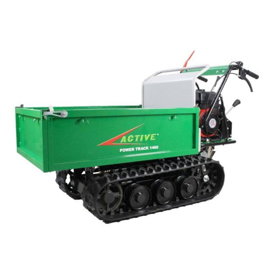
- Page 1 POWERTRACK 1460 MONTAGGIO KIT PALA NEVE SNOW SHOVEL KIT ASSEMBLY ART. - REF. 800940...
- Page 2 CONTENUTO DEL KIT - KIT CONTENT Prima della rimozione del cassone, segnare l’ingombro per la successiva applicazione della fascetta ferma tubi. Before removing the tipping body, mark the overall dimensions for the subsequent application of the pipes clamp.
- Page 3 Praticare un foro passante - Ø 8 mm. Drill a through hole - Ø 8 mm. Rimuovere le due viti del carter manubrio. Remove the two screws from the handlebar cover.
- Page 4 Fissare il gruppo innesti rapidi sul carter manubrio utilizzando la vite 8x25 e la rondella in dotazione - applicare frenafiletti forte. Fix the quick coupling unit on the handlebar cover using the 8x25 screw and washer supplied - apply strong threadlocker. Assicurarsi che il gruppo innesti rapidi sia in posizione orizzontale e che non possa ruotare.
- Page 5 Rimuovere la fascetta dei tubi del cilindro idraulico. Remove the clamp of the hydraulic cylinder pipes. Rimuovere le quattro viti del coperchio scatola marce (due a destra e due a sinistra). Remove the four screws from the lever box cover (two on the left side and two on the right side).
- Page 6 Rimuovere la vite sul retro della scatola marce, per liberare la fascetta stringitubi sul lato opposto. Remove the screw on the rear of the lever box to release the hydraulic cylinder pipes clamp on the opposite side. Rimuovere i tubi dalla centralina oleodinamica (ATTENZIONE:POTREBBE FUORIUSCIRE OLIO).
- Page 7 Rimuovere la vite di fluttuazione dalla centralina oleodinamica. Remove the float screw from the hydraulic unit. Applicare il rubinetto flottante alla centralina oleodinamica. Apply the floating faucet to the hydraulic unit.
- Page 8 Bloccare i tubi idraulici del kit innesti rapidi, utilizzando la fascetta precedentemente rimossa. Block the pipes of the quick couplings kit, using the clamp previously removed. Bloccare i tubi idraulici del kit innesti rapidi alla scatola marce, utilizzando la fascetta precedentemente rimossa. Block the pipes of the quick couplings kit to the lever box, using the clamp previously removed.
- Page 9 Riavvitare le quattro viti del coperchio scatola marce (due a de- stra e due a sinistra). Screw again the four screws of the lever box cover (two on the left side and two on the right side). Se gli occhielli non sono orientati correttamente (fig.A), ruotarli come mostrato in figura B.
- Page 10 Fissare i tubi idraulici del kit innesti rapidi al rubinetto flottante. Fasten the hydraulic pipes of the quick couplings kit to the floa- ting faucet. Applicare gli innesti rapidi maschi, precedente rimossi dalla centralina oleodinamica, sui tubi idraulici del ribaltamento cassone.
- Page 11 RISULTATO DELL’ASSEMBLAGGIO - ASSEMBLY RESULT Posizionamento tubi idraulici kit pala neve - 1 Positioning of hydraulic pipes for snow shovel kit - 1...
- Page 12 Posizionamento tubi idraulici kit pala neve - 2 Positioning of hydraulic hoses for snow shovel kit - 2 Allentare la fascetta dei tubi del cilindro ribaltamento cassone. Loosen the pipes clamp of the hydraulic tipping body cylinder.
- Page 13 Aggiungere la fascetta per fissare i tubi del kit pala da neve. Add the clamp to secure the pipes of the snow shovel kit. Assicurare i tubi idraulici del kit pala neve al telaio, utilizzando le fascette in dotazione (i tubi non devono entrare in contatto con i cingoli).
- Page 14 Rimuovere la vite della fascetta. Remove the clamp screw. Aggiungere la fascetta in dotazione per fissare i tubi del kit pala neve (ruotare secondo le esigenze). Add the provided clamp to secure pipes of the snow shovel kit (rotate as needed).
- Page 15 Opzione 1: forare e filettare la piastra sotto la linea precedentemente tracciata. Avvitare la fascetta in dotazione per fissare i tubi del kit pala neve (utilizzare la vite in dotazione). Option 1: drill and thread the plate below the previously drawn line.
- Page 16 Allentare alternatamente le viti di tensionamento del cingolo, e rimuoverle completamente. Alternately loosen the track tension screws, and remove them completely. Sostituire le rondelle più grandi, con quelle più piccole fornite in dotazione con il kit pala neve. Replace the larger washers with the smaller ones supplied with the snow shovel kit.
- Page 17 Centrare la piastra inferiore attacco pala. Center the shovel attachment bottom plate. Fissare la piastra inferiore attacco pala, serrando le viti da 12 mm. Avvitare le viti da 16 mm per regolare la tensione dei cingoli. Secure the shovel attachment lower plate, tightening the 12 mm screws.
- Page 18 RISULTATO DELL’ASSEMBLAGGIO - ASSEMBLY RESULT Rimuovere le 3 viti 8x25 sulla parte superiore del supporto cassone. Remove the 3 screws 8x25 on the upper part of the tipping body support.
- Page 19 Posizionare il supporto superiore della pala senza serrare le viti. Place the upper shovel support without tightening the screws. Bloccare il supporto utilizzando i 3 perni in dotazione. Lock the holder using the 3 pins supplied.
- Page 20 Serrare le viti della piastra di attacco superiore della pala. Tighten the screws of the upper shovel attachment plate.
- Page 21 Fissare i tubi idraulici sul cilindro pala neve. Secure the hydraulic pipes on the snow shovel cylinder. Attacco braccio pala neve. Snow shovel arm connection.
- Page 22 www.active-srl.com...
Need help?
Do you have a question about the POWERTRACK 1460 and is the answer not in the manual?
Questions and answers